Counterboring (1.5 hrs)
As much time as I have put into these mounts, they’ve got to be worth at least $10,000 by now!
The bad news is I am not quite finished with them yet and, as in most things, the detail work is taking up as much time as it did getting them to this point.
The latest “machining opportunity” happened because of a design flaw. Well, flaw might be too harsh a word, nevertheless it is an issue that could have been nullified with more careful positioning of the bolt holes pattern.
You see, the L channel that I used for constructing the landing gear mounts has a rounded inner corner, and this interferes with the 0.5” (12.7 mm) washers that are installed with the mounting bolts.
 |
| Washer and bolt unable to seat properly |
This situation is clearly unacceptable, as it would prevent proper tightening of the bolts.
There are a few ways to deal with this problem. Obviously, I could have moved the bolt holes further in, thus eliminating the issue altogether, or ground some material off of the washers, but neither option appealed to me. I thought that a more elegant solution, respectful of the original design positioning of the bolt holes, and more challenging to my beginner machinist capabilities, would be to counterbore the holes.
Having never even seen a counterboring mill, I had to begin by educating myself first (there goes that word again).
It turns out that a regular 0.5” mill could do the job, kind of. There are a few issues with this sort of approach. First, as the mill descends on the L channel and starts cutting on the sloping surface, it gets deflected, and a poor cut pattern results. Second, and more important in this particular application, because the mill cuts with its outer edges first, it leaves a round groove that mars the surface of the part.
A counterboring mill is designed to deal with these situations, by having a pilot that fits in the hole to prevent deflection from, and ease alignment with the hole, and by cutting more evenly when plunged.
 |
| Counterboring mill |
If you were to look for such a device on eBay, you’d have to be careful, because of the wide variety of configurations that exists. Some mills have an integral pilot, while others allow you to remove it and exchange it for one of a different size, giving you more flexibility. This last one is the type I chose, since I could not find an individual 1/2” counterbore with a 1/4” (6.35 mm) pilot for sale.
Unfortunately, even within this subclass, there are more configurations, some of which are not suitable to what I am trying to accomplish. Going for the least expensive set, got me a set of counterbores unfit to my situation, because they were too short and the mill holder ended up contacting the part before the cutting edge did.
 |
| Wrong counterbore purchase |
I had to return them, and it cost me $35 between shipping and restocking fees. The second set I purchased was more expensive, and had more pilot/counterbore combinations by using different shaft/hole diameters. Unfortunately the 1/4” pilot had a shaft size too thin for the hole in the end of the 1/2” counterbore mill. Facing more shipping charges, more restocking fees, and needing to buy an even more expensive set, I decided to manufacture an adapter to slip between the mill pilot hole, and the pilot shaft, to take up the difference in thickness.
Having plenty of aluminum tubing scrap, I decided to repurpose an old threaded rod. I chucked it up to the lathe, drilled it, turned it, then cut it to the proper length.
 |
| Creating an adapter sleeve |
 |
| Pretty tight turning! |
 |
| Sleeve in position on the pilot's shaft |
 |
| Exploded view of final assembly |
Presto, problem solved.
I love this stuff!
So, here’s how the pilot fits in the 1/4” hole...
 |
| Highlighting the pilot's purpose |
... and here’s the complete counterbore mill in position (on the wrong hole)...
 |
| "Look Ma'... no hands!" |
With the latest dilemma over, the next order of business became figuring out how to use the tool consistently, removing as much material as necessary, but not a gram more. I decided that to achieve this goal, I’d have to stop exactly 0.001” (0.0254 mm) short of the flat portion of the L channel.
The solution I have come up with, while it might not be the most high-tech one, proved itself very effective.
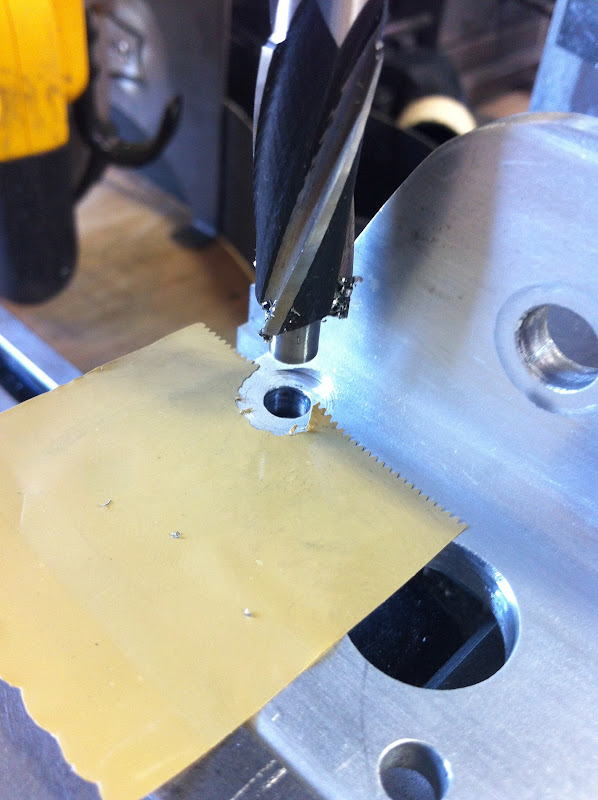
It turns out that brown packing tape is exactly 0.002” (0.0508 mm) thick.
 |
| I suppose they mean it when they say "2 mils" on the package! |
So, I decided to use the tape as a “proximity alert” during the cutting operation. I did so by putting one layer of it by the hole, and stop advancing the mill when the tape got ripped up.
 |
| High tech mill stop |
 |
| Eureka, it worked! |
I highly recommend this method because it is easy, yet provides reliable and repeatable cuts with extremely high level of precision, as you can see in the following video.
The counterboring operation turned out to be quite anticlimactic, and all the 8 holes were finished in just a few minutes.
The final product of this operation is a proper bolt/bracket interaction that enables bolt and washer to sit flat, and allow adequate torquing during final assembly.
 |
| A perfect world once again |
No comments:
Post a Comment