Chronicling my Long EZ construction (and a few other things).
Disclaimer
This blog is for entertainment purposes only, and is not meant to teach you how to build anything. The author is not responsible for any accident, injury, or loss that occurs as a result of reading this blog. Read this blog at your own risk.
I was trying to keep this a surprise, when my neighbor walked by and asked… “What are you working on?”
“Nothing!” I replied, hoping to conceal the evidence, only to arise my wife's interest.
Trying my hands on something more interesting
Luckily she enthusiastically pronounced the part to be a perfect fit for our mailbox, snatched it, and ran outside.
“Eureka!” I thought.I really had had no plans on what to do with it. We all ran out after her.
"What you think of this?!"
Everyone loved the idea.
Now it was up to me to figure out how to mount it. I wanted it on the mailbox for good, so double-stick tape didn’t sound permanent enough.
So, I went out and bought an 8-32 threaded rod from Lowes, put it in my CNC mini-lathe and programmed it to cut ¾” sections. I cut four, so that I could make another EZ for the backside of the mailbox.
After drilling and tapping two holes in the strakes and screwing the rod sections in, I set it on my table, looked at it, and started laughing at the tiny Long EZ in the grazing position.
It even kneels like a Long EZ!
I TIG welded the threaded rods to the EZ, painted it white (of course), drilled a couple of holes in the mailbox, and Voila!
"See honey... I told you, I'd eventually use the TIG welder on something useful!" 😁
One gear leg "down and welded", one more to go.
If only flipping an EZ was this EZ 😅
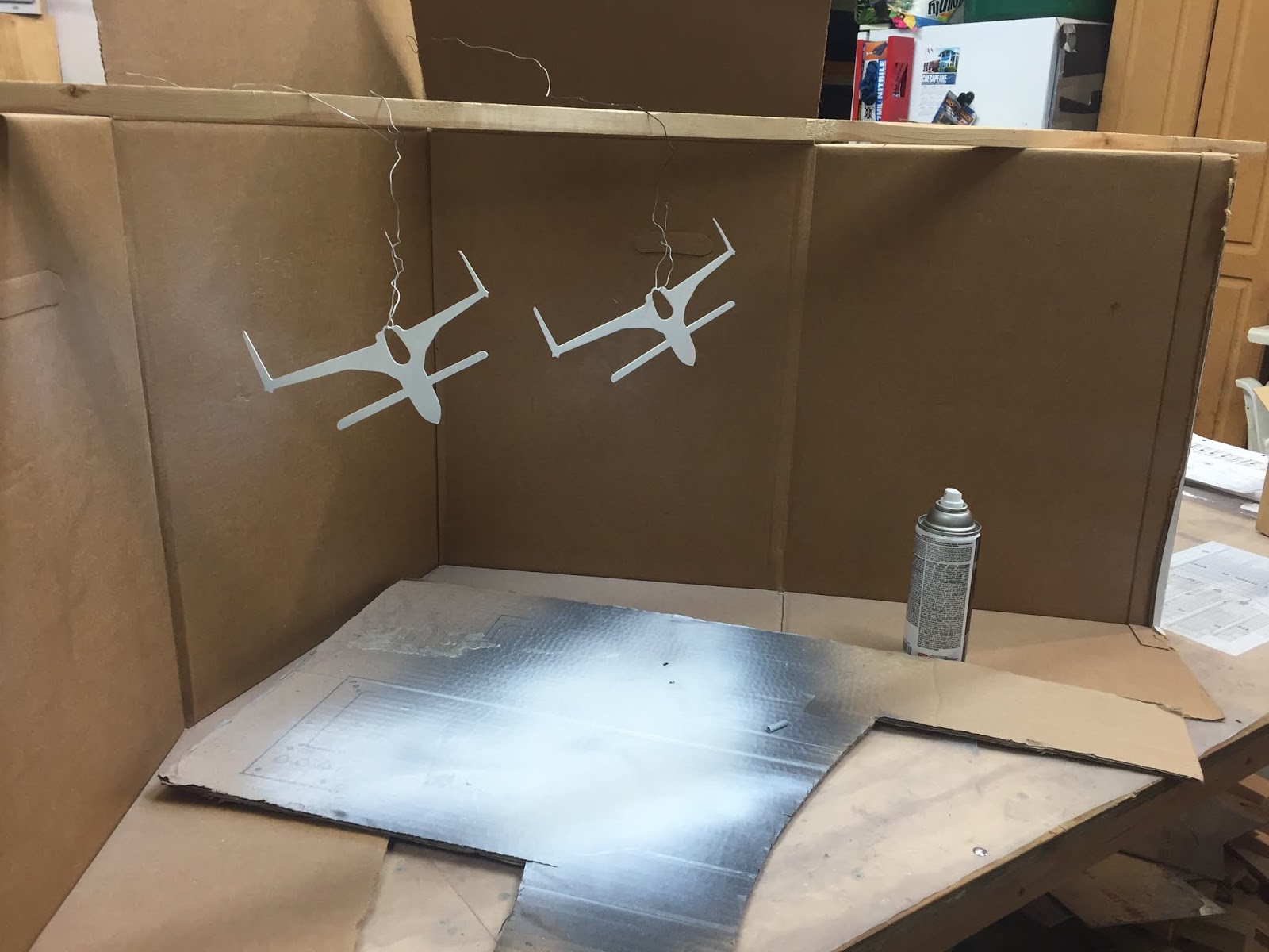
A little sanding, and we were ready for paint.
Strictly white of course, per Rutan instructions.
It was a little like having a fly-in on my dinner table!
Here's the finished mailbox
I used extra nuts on the outside to space it off the mailbox for a more 3D effect.
Back side too, in case the mailman ever looks in the rear view mirror. 😁
I used extra nuts on this side as well
Mailman's view
Let there be no doubt a Long EZ builder/pilot lives here
This project consumed a couple of days for various reasons, but the plasma cutting portion of it only really took about thirty seconds of that. Regardless, I think the mailbox looks awesome now, and what's more important... the boss agrees.
“I don’t always have a back seater, but when I do she's got to have two big… outlets!“
Jonathan Goldsmith aka the most interesting man in the world
Really, nowadays this sounds like such a no-brainer. USB outlets are cheap, plentiful online, and so useful. One can keep a passenger entertained (and quiet) for hours at a time, without any complaints of dead cellphones upon arrival.
And when the GIB (Guy/Girl In Back) is another pilot, you can turn them loose on Foreflight, and have them be useful all the way there and back.
I recall, my first Rough River trip with Wade in 2016. On that first cross-country flight the vacuum pump failed (in VFR weather) right after climbing above the cloud deck (pre-instrument panel upgrade). We continued flying westward on top into improving conditions.
Wade and me at a fuel/restroom stop
A bit later, his tablet's battery also died, so I handed him the one I was using up front, but because of the lack of power in the back seat that one eventually died too. For the rest of the flight, traffic alerts and moving map were only available through my iPhone (connected to JT's Main Bus). While definitely not an emergency, the situation was certainly less than ideal, and a bit inconvenient.
But it doesn’t have to be that way anymore, because today I am installing a twin USB outlet behind my seat for the GIB's use.
I was originally going to mount it horizontally, right beside the fire extinguisher behind my right shoulder, but I discovered that this location could be troublesome. When I tried closing the canopy, its thin brace tube (behind the headrest) swept a vertical plane that would hit any plug attached to the outlet.
You can imagine how the brace tube swings down with the canopy
Even worse, it could become difficult if not impossible to open the canopy until whatever device connected to the outlet got unplugged.
That wasn’t going to fly!
My second best location turned out to be pretty close to number one. I chose to install the outlet almost vertically, by attaching it to the front seat back surface.
The volume above the servo was already dead space
The brace tube doesn’t swing that low, so the outlet can be in use at any time without fear of damage, or entrapment. Also, by placing it above the pitch servo, I recycled some unusable space, and took advantage of existing wiring runs and ties.
Leftover firewall plywood recycled for yet another project
The plywood was floxed to the front seat-back
Two wood screws hold the outlet in position
With the Master Switch ON, the outlet is automatically powered.
Wiring the outlet to the Master Bus allows me to automatically shed its load in case of alternator failure, after switching to the Essential Bus.
I am now looking forward to long more relaxing flight with a much happier GIB.
What I’ve been able to cut with this table so far is more than good enough for the way in which plasma cutters are normally employed, making parts for welding jobs, or components for other types of loose fitting assemblies. Because these parts do not usually require the high precision of a CNC mill, it makes them suitable for the plasma cutting process.
The million dollar question still remains though… is this CNC/plasma cutter combination accurate enough to produce component to size right off the table?
As usual, the answer is not as clear cut (pun intended) as one would like, and while it might eventually be that accurate, there are so many variables at play in this type of machine, that time and practice will be needed in order to home-in to the ideal settings.
First there is the question of the table accuracy. Nothing else will matter if the table won’t reliably get the cutting tool to the exact location time after time, and the cut will never be right regardless of whether one is using a plasma cutter, a laser beam, or… whatever!
Then there is the material. I have already found great differences in the way aluminum reacts to being cut compared to steel.
Then there is the thickness of the material, the dimension of the part being cut and how heat is dissipated (or not), use of a water table (or not), the kerf (width of the plasma jet), the shape of the kerf (like a cat’s iris), the height of the nozzle from the material (engaging different parts of the kerf), the amperage, the type of nozzle, the state of the consumables, the air pressure, the dryness of compressed air, the travel speed of the cutter, the acceleration/deceleration of the table, the entry/exit point of the cut, lead in/out distances and angles, the direction of the cut (hard to believe, I know), the pierce delay time, inside corner vs outside corner, to say a few.
How amperage and travel speed can impact dross formation on the same material (parts flipped up)
I decided to begin with the basics, and start testing the CNC table to try to discover, and then minimize any errors it might have. The two big ones to be on the lookout for with any new CNC machine are backlash, and size distortion(I made up this last name).
Although the Langmuir table uses ACME screws, the preloaded nuts cut the backlash to 0.001” or less, so we are all good there, and since I have already explained backlash here let's move on to size distortion. Size distortion happens when you ask your CNC table to move, say… one inch, and though the DROs (digital read out) say the tool did move one inch, the actual measurable amount is different. This is usually caused by having the wrong stepper motor’s steps per inch selected, AKA how many impulses the computer transmits to the stepper motor to get one inch of machine travel.
As far as Steps per Inch, the Mach3 (controller software) Langmuir’s configuration defaults to 12800 spi (steps per inch) which is mathematically correct, but does not take into account the physical reality of the components. The only way to account for all the intangibles, is to conduct many a test on the table, and modify settings accordingly until the error is minimized, or eliminated.
The way to do this is to gather the biggest object (to minimize compound errors) that can fit on the CNC table and that can be measured very precisely with a caliper, and try to measure it once more using a dial indicator in place of the cutting tool. Any difference between the two measurements is an error due to the steps per inch selected, and needs to be iteratively adjusted and retested, until the error approaches zero.
Measuring the size of my turn table using a dial test indicator and Mach3's DROs
Indicator is set to zero at point #1, then moved in Y+ to #2 until it reads zero again (Yes I know it's 0.0005" off in this photo)
Testing in X direction
New Y axis SPI value 12818 found after a series of 9 test measurement runs
Y axis SPI value set to12818 in Mach3
New X axis SPI value 12872 found after a series of 7 test measurement runs
X axis SPI value set to12872 in Mach3
With the more accurate Steps per Inch figured out, the table is now as precise as it’s ever going to be, and although it’s still a couple of thousands off (we are really asking the cantilevered gantry setup for a lot), this is quite good enough for any of the work I am planning on doing with it.
I might have mentioned that the main thing I wanted to be able to do with this machine was to cut my own instrument panels (in seconds instead of days), so let’s try doing just that on an expensive sheet of 0.090” 2024 Aluminum. Bear in mind this cut was done before the above adjustments were completed, and before figuring out more reasonable speeds and feeds.
Plasma cutting an instrument panel
Pretty exciting stuff, right?! Well, I thought so, at least after I remembered about the plastic on the aluminum sheet.
Doh!
With this first panel I did have to do a bit more filing than I was hoping for. Hopefully, with the newer settings I was offered online and a little more experimentation, I will be able to shorten the post-processing phase.
Anyway, here are a few pictures of how the panel turned out, I think you will approve…
Instrument panel #4 right off the plasma table
Instrument panel #4 back side
Instrument panel after removing dross
Testing hole sizes and locations
Plasma table is going to have to do a lot better than this! These rounded holes created a lot of hand filing for me.
Old and new Cleco'ed together to aid in hand filing
Panel #4 de-burred, drilled, and filed
Test fitting "front office" items
Designing a pass-through for pitot/static hoses
Pitot/static connectors captured on one side
Pitot/static connectors captured on both side
Holes added in back plate to move pitot/static from the side entry to the rear entry
Relocating connectors to back plate will allow panel to be removed as a unit from the cockpit side
Pitot/static rakes
A small amount of wiggle in the pass through connectors is ok
Pitot/static connectors locked in
A wider view of the rakes and connectors
Pitot/static lines to the EFISs
Pitot (red) and static (white) lines to the Mini EFIS
Instrument panel Alodined...
... and painted
The final product
My self-contained IFR Instrument Panel concept
D-subs connect to sensors, servos, and radios I have installed throughout the plane.
It's awesome being able to unbolt the panel and take it home for maintenance or upgrades, all in a few minutes.
Time to get these harnesses sorted out!
Wire bundles and pitot/static lines installed
Fully connected panel sitting on the pilot seat ready to be pushed in place


