JT’s improvements continue
If you fly long enough, you too will eventually experience a faulty transmit switch.
There are many reasons why this might occur, like getting hammered all day long, but it is generally just a minor inconvenience to be fixed upon one's return home, since most us hardly ever even need to talk on the radios.
Flying IFR though, communication is the name of the game, and anything that impairs this ability might lead to filling unpleasant paperwork at the end of the day, depending on the amount of ATC involvement needed, if you know what I mean.
Boeing obviously thinks having alternate ways of transmitting is very important, as I counted at least 10 Push To Talk (PTT) switches in the cockpit last time I flew a B767. So, I decided to add a second PTT switch on JT's throttle lever for redundancy, and to allow the left hand to pick up some of the work when the right one is busy with other tasks, like writing down clearances.
One extra feature of this additional switch will be a direct connection to the PTT circuit of the radio, bypassing all other wiring bundles, and serving as a backup way of transmitting.
Unfortunately the current throttle lever couldn’t support a PTT button, so I had to design a new one that would.
 |
| Proposed new throttle lever |
 |
| The switch will be the same kind I used in the Push To Test panel annunciator |
 |
| A steel boss will be welded to the tab. The handle will mount to it. |
It all started with leftover a 4130 steel tube, and a 2024 aluminum bar.
 |
| Nothing ever goes to waste in a machine shop |
3D printing the end cap allowed me to visualize and play around with what I was trying to produce, and confirmed its dimensions would work.
 |
| Testing the business end in ABS |
With the dimensions finalized I fired up the CNC mini-lathe and went to work on the aluminum bar.
 |
| The aluminum end cap is taking shape |
 |
| End cup finished with PTT switch |
Not sure of how long the lever should be, I left it extra long, to be shortened later.
 |
| Handle assembly |
As in my drawings, I welded a boss to the replacement throttle lever tab which will be used to secure the actual handle.
 |
| Boss welded to the tab |
 |
| Boss back side |
 |
| Handle mounted to the boss |
 |
| Oversized handle assembly |
 |
| Old and new throttle levers |
Of course the new lever was ridiculously big, and though it did feel great to work with, it had obvious drawbacks…
 |
| This size handle covers up the radio... |
 |
| ... and cannot be pulled back to idle. |
… so I went shorter, much shorter.
 |
| This looks more the part |
Shorter was definitely the way to go, but now it was a bit too small to handle comfortably, so I decided to double it up like the original one. The problem with this idea was that to look good, the bosses on both sides would have to be perfectly lined up and concentric, not an easy feat with welding.
After mulling it over for some time, I decided to make a welding jig to hold the second boss concentric to the first one while I welded it. This second boss would be slotted to allow the PTT wires to come out of the bottom.
 |
| Using the cut off handle piece as a jig |
 |
| Sliding the new boss into the welding jig |
 |
| New boss perfectly aligned to the old one, ready to be welded. |
I started with a couple of tack welds in the jig…
 |
| TIG welding a couple of tacks |
 |
| The two tacks will hold the boss in place for final welding |
… then took it out of the jig to do the actual welding.
 |
| Second boss being welded to the tab |
 |
| Welding completed, bosses lined up and concentric. |
The jig did the trick, and both sides of the throttle came out looking parallel and concentric.
 |
| Both sides of the throttle handle mounted |
 |
| I'd say the welding jig was a good idea |
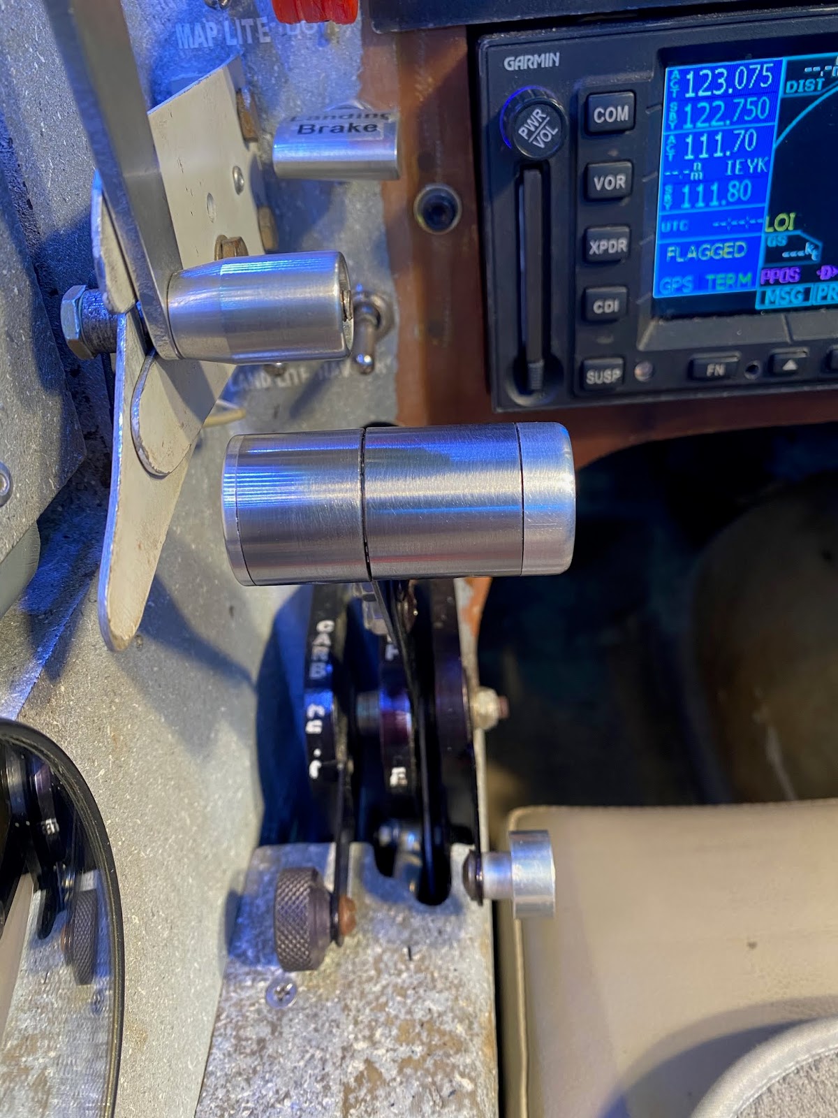
The PTT wires will eventually come out of the bottom, and be routed through the throttle panel in a manner yet to be determined.
 |
| I staged this photo to show where the wires will exit the throttle lever |
Meanwhile, before going too far with electrical connections, it was time to put it in the plane and go fly around a bit to make sure no unforeseen issues would crop up.
 |
| The new lever is no taller than the old one was |
 |
| There is still room to shorten the right half further. Size however, rather than symmetry, was the only requirement. |
 |
| Throttle at idle |
 |
| Clearing the canopy latch bolt was the limiting factor on the outboard side. |
I’m glad to report the new throttle lever has been working great over the past half a dozen flights, so I shall move on to wiring it in Part 2.