Chronicling my Long EZ construction (and a few other things).
Disclaimer
This blog is for entertainment purposes only, and is not meant to teach you how to build anything. The author is not responsible for any accident, injury, or loss that occurs as a result of reading this blog. Read this blog at your own risk.
I’ve
been wanting to do this mod for such a long time that when my friend Shane
asked if I had ever considered it, I just had to drop everything else in order to enter this rabbit hole.
Electrically actuated landing light
If
you aren’t intimately familiar with the LongEZ design, you might be
excused for not knowing that the only available landing light is mounted
in the belly of the plane, right between the pilot’s knees, and it is
extended manually into the slipstream using a short handle that moves a
much longer lever, that in turn gets captured with an over-center mechanism.
This
simple device works so well that, had I not been such a sucker for a new
chase, this mod might still lay unrealized in a dark corner of
my mind.
My good friend Walter's landing light assembly (circa 1980)
JT's landing light assembly (retracted)
JT's landing light deployed
Landing light from below and behind
Landing light business end
So, why all of the excitement over rethinking something that already worked?
Well, after flying JT for some years I have come up with a short list of minor annoyances
that I thought I might be able to address. It would require a lot of R&D
work, and many uncomfortable hours upside down in a cold hangar, but as luck
would have it, with JT already in my heated garage and the airlines not
flying me much, it was a now or never situation.
An
electrical actuator could be a welcome addition for a number of
reasons...
With a switch right on the stick I would never have to
take my hand off the controls during an approach.
There would be no need to
loosen the iPad mount (also between my knees) and move it out
of my way in order to reach the landing light control lever. I also would not have to reposition it back anymore in a
way that allows me to read my approach plates without covering up any of the panel's instruments.
The landing light
wouldn’t become harder to deploy just because I'm coming in a little faster, or at
least I wouldn’t have to struggle with it.
I would avoid bumping
my head into JT’s low profile sloping canopy when reaching for the lever.
New
capabilities could be introduced with this design, like making it adjustable in such a way that the light
would shine parallel to the fuselage for taxing, and at a downward
angle for landing.
While at it, why not include a flasher module to
make it easier for other pilots to see me.
Lastly, I could close the gaping
hole in the belly, and stop annoying air pressure fluctuations from buffeting my ears all the way to touchdown.
While this issue appears to be very airframe
specific according to my conversation with other LongEZ owners,
in JT it produces very noticeable pressure waves in the cockpit, much
like driving down the highway with a rolled down passenger window. You
know what I
mean? Definitely not a safety issue, but annoying as hell.
Anyway,
I figured that if I could improve these aspects, I would probably use
the light more often, and reap multiple safety benefits at once, but
let me cut to the chase and show you the finished product first, then
you can stick around if you’d like to see the details of this mod.
Good builder gone rogue
Back
from the future now, the new light has proven itself trouble-free
over the past six months, and I haven’t had any issues deploying it to
speeds up to 135kts (haven’t tried any faster).
So, what are the components of this mod?
After
going up a few blind alleys wasting money on components that didn’t
deliver, I settled on a microprocessor controlled linear actuator. This allowed me to define the beginning and end of travel,
sidestepping the geometry problems that vexed my fixed throw actuator installation attempts.
After
calculating the forces involved in deploying the light at 120kts plus a
safety factor (thanks Ary), I matched my requirements to the Actuonix L16-100-150-12-P-LAC.
Here's what I ordered from Actuonix
This is what you get
The
L16 actuator is a self-contained linear motion device with
position feedback, and end of stroke limit switches. Several gear ratios
are available to give you varied speed/force configurations. I chose
the 150/1 gear reduction ratio model because speed at deployment was more limiting than speed of deployment.
The
L16 is designed to push or pull a load along its full stroke length,
and the speed of travel is influenced in part by the load applied, so higher
airspeeds might slow down the landing light deployment. When power is
removed the actuator will hold its position, unless the applied load
exceeds the back drive force.
I
used the –P actuator as a linear servo by connecting it to
an external controller, in this case the Actuonix LAC board, but one
could run it through an Arduino if so inclined. This control
board constantly reads the position signal from the L16, compares it
with the input control signal, then drives the actuator to move in
whatever direction necessary to reach the commanded location.
I
will include here three different wiring diagrams for three different
installation scenarios. Like everything else I post on this blog, you
may use these at your own peril, as they might be worth what you paid
for them.
First
is the generic two positions up/down wiring with no position LED
indicator. This would be used if one merely wanted to replace the manual control
lever with the linear actuator.
Most basic installation
Next
diagram shows the wiring changes required to add a separate taxi and
landing light positions, plus a position status LED indicator. Note that
the presence of a position indicator alters the wiring of the actuator to the board.
Got this working on the bench first
Wires from the actuator had to be reversed to make the LED indicate correcctly
Lastly,
JT’s actual wiring diagram including ON/OFF microswitch,
flasher unit, flashing pattern change button, and three-way
arming switch.
JT's actual wiring was complicated by, and had many splits due, to the removable instrument panel.
Now, let’s move on to the details of the installation.
One
of the best features of this installation is the fact that it reuses
all of JT's existing mounting points, making a retrofit much simpler.
This is
made even better by the fact that the actuator is not much wider than
the control rod it replaces.
A very small actuator that can still pack some torque
Had to file the fuel selector mounting plate slightly for clearance
Fit is perfect with minimal modifications
This rod-end needs some serious beefing up
I designed and 3D printed a box for the actuator control board.
Pot-chutes deliver the screwdriver tip right to the potentiometer control screw
Four holes for as many pots on the circuit board. This LAC board is highly customizable
My Zortrax M200 hasn't stopped amazing me since day one
Wouldn't wanna loose that tiny driver!
I mounted the box in the nose where I had some free space, a decision that would introduce some problems (as you shall see later).
Found some unused real estate on the nose gear cover
Dsub connectors are the way to go here
Unfortunately proximity to the GPS antenna proved troublesome (more info on this at the end)
Extension of the actuator arm in "landing light" mode is controlled by a
10KΩ potentiometer. I wanted to position this device on the instrument panel close to my
throttle hand, so I could make minor adjustments to the light's angle without moving my hand off the throttle lever.
Had to build the pot in CAD from scratch since no files are available from the manufacturer
This worked very well given the tight confines of the panel
Since
I didn’t have a knob that fit such a small potentiometer, I designed
and 3D printed one, and for once it fit perfectly the first time 😀.
3D printer to the rescue (yet again)
Fit like a glove 😁
A sliver of aluminum tape after painting it black tricked it out
A strip of landscape fabric over the front face eliminates dust intrusions
To
save from mounting another ON/OFF switch on the panel, and having to
remember to toggle it, I made the light turn itself on and off using a
micro-switch. I had a few
laying around, but the one I took off my old busted TIG welder pedal fit
the
bill perfectly.
Building a LongEZ will turn you into a recycling machine
Microswitch activated by a hinge rivet
Light activation scheme
Choosing
between different lighting angle positions (up, landing, and taxi) is done through a
switch on the stick, once again eliminating arm movements on final
approach and right after landing.
I should have labeled it "LT UP/OFF" since this switch determines light position
The only drawback for this actuator... the one thing that is totally unacceptable, is
the bottom rod-end plastic connector. This piece is made out of thin hollow plastic,
and it is flimsy and completely inadequate for the job at hand.
The Delrin spacers (white) are temporary
This rod-end (black) has got to go!
I decided to remake it out of a 2024 aluminum rod I had on hand. It turned out to be quite a lot of work for such
a tiny part, but the resulting safety upgrade was well worth the effort.
Bar was drilled through on the lathe first, then moved to the mill.
Bottom features were machined first
Part was then removed...
... and flipped on its back...
... then the top features were machined...
... until the stock was completely removed.
With threading and some cleanup left to do.
New rod-end is definitely much stronger and safer than the old plastic one
Making the rod-end
The new light was working as advertised by this time, so I moved on to the optional flashing mod.
The
Wave Wagger modulecan control two independent light channels, but given the single light on JT
I ended up using only one of the two channels. I suppose technically I couldn’t really call this a
wig-wag light, perhaps wag-wag would be more appropriate 😆. From a
distance however the effect is pretty much the same, and the thirty-six
preprogrammed modes (selectable through a push-button) do keep the flashing interesting at all times.
Even
though the module is very light, I was determined to find some room in JT's nose, where
any weight helps move the CG toward the middle of the range, and the length of the wiring is minimized.
A 131 grams addition that will greatly improve safety
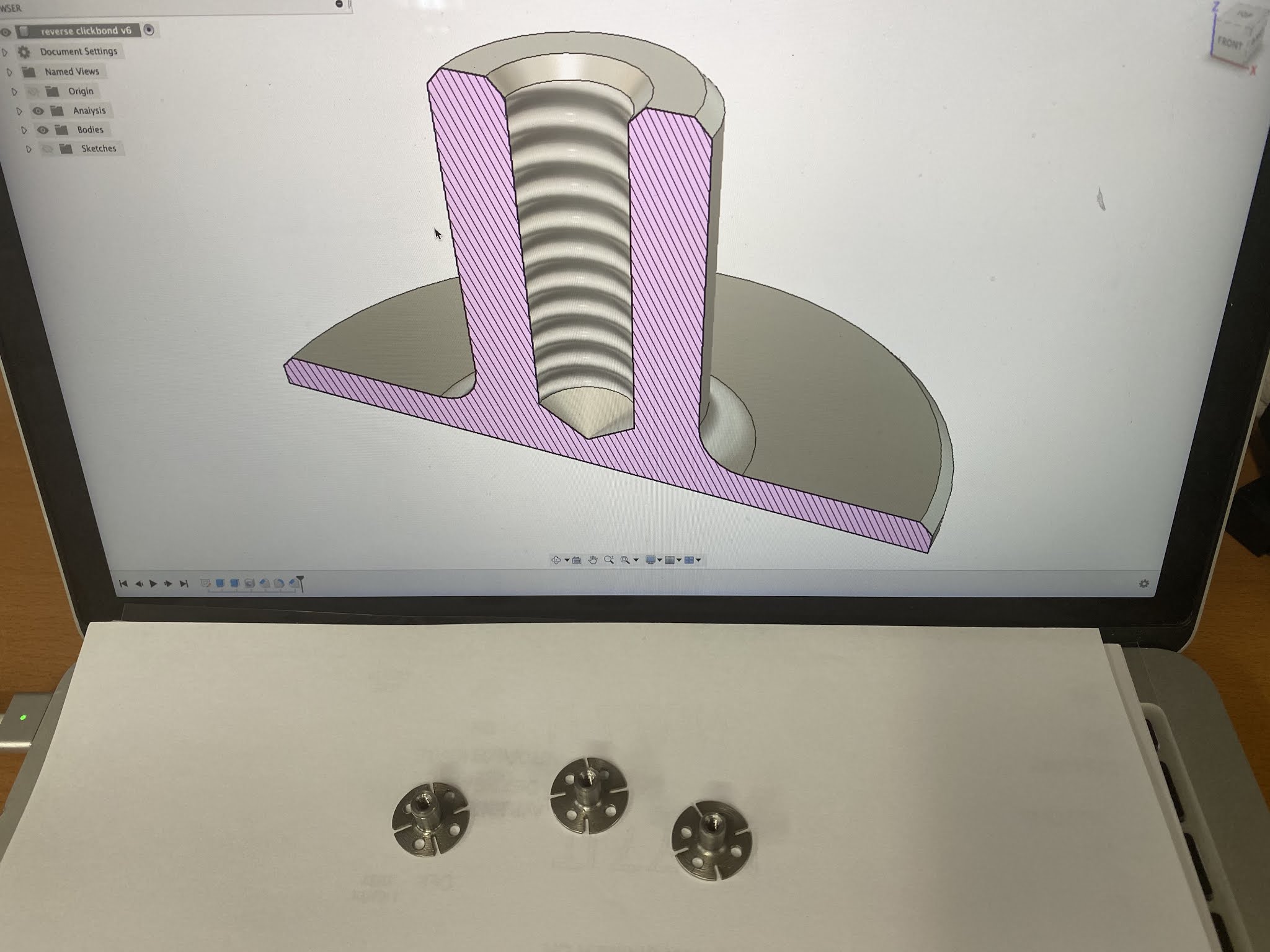
The
only room left in the nose was on the sidewall so, in order to mount it
vertically, I had to machine some custom stainless steel clickbonds on
the CNC minilathe.
Making custom clickbonds
Clickbonds right off the lathe being test fitted
Will need to rough up these surfaces for the flox to stick
Clickbonds design
Ready for use after a little further manipulation
With the clickbonds made, I began installing them near the Essential Bus fuse box.
Nice little clear space of just the right size
Masking everything is paramount when epoxy is involved
Even the flasher module gets temporarily masked with clear tape before floxing
Flasher unit mounted (before wiring)
To keep with the theme of reducing the need to remove my hands
from the controls when close to the ground, I removed the gear/canopy warning buzzer from right in front of the
throttle, and after 3D printing a suitable adapter, I installed a redbutton that cycles through the 36 flashing
sequences in its place instead.
Repurposing the original buzzer mounting hole
The switch is seldomely used, and then only when throttled back. This protected position is perfect in many ways.
The buzzer was relocated just a couple of inches behind the panel, and it is still loud and obnoxious as always.
The last part of this reinterpretation of the landing light would be to produce a cover for the gaping hole in the floor.
Hole under the thigh support that opens when the light is deployed
As always when dealing with epoxy... mask everything.
One cannot be too careful
Back of the landing light
Landing light
Landing light minus brackets held closed for glassing
A block of foam on the outside is holding the light in the up position while glassing
Plastilina cleaned up, test fitting of the two cover halves.
Covered hole as seen from below
One issue I hadn’t considered was that
mounting the actuator control box so close to the GPS antenna caused the
GNS480 to loose its lock to all satellites every time I powered the board, with the
consequences you might imagine. Because I only turned on the light shortly before landing, this issue took some time to sort
out.
The
solution turned out to be the addition of shielding inside and outside
of the 3D printed box. While this did take care of the reception problem, I
should have probably just used a metal box to begin with, or moved the
box further from the GPS antenna.
Aluminum tape installed inside the box to limit radio frequency interference
Aluminum tape applied under the box and to the lid
Restoring GPS reception
I
have enjoyed using my taxi/landing/recognition light for quite sometime
now, and I am very happy with the results. I understand this mod might not be for
everyone, but I find myself using JT's light during every approach, every
landing, and every taxi operation now, and I have been told I am easily seen miles away from the airport.
So, I’m giving this mod Marco’s two thumbs up of approval 👍🏻👍🏻.

