Chronicling my Long EZ construction (and a few other things).
Disclaimer
This blog is for entertainment purposes only, and is not meant to teach you how to build anything. The author is not responsible for any accident, injury, or loss that occurs as a result of reading this blog. Read this blog at your own risk.
The leading edge section of the canard is made out of two 4 foot long pieces. These have been match-drilled to the main foam cores with a 1/4” drill. Using sharpened 1/4” dowels I should be able to reassemble them, and maintain the original alignment of the leading edge to the main cores. Since the holes were randomly drilled through the core/leading edge assembly by Eureka, the dowels make it impossible to mistakenly swap them.
Wade gave me the 10 dowels, but they needed to be sharpened, and since they are roughly the size of a pencil, I put them in my drill and ran them through a pencil sharpener.
This was quick and painless
Dowels sharpening the easy way
The next step was to find the holes in the core foam under the fiberglass, and open them up to 1/4”. That sounded pretty easy, but proved quite the opposite since the dark epoxy made it hard to see anything below it, and the closer to centerline, the more the plies of glass, and the harder to see.
Using a round file to open the dowel holes after drilling the fiberglass first
Anticipating this, I took careful measurements of all hole locations before fiberglassing, but being late at night I still managed to drill one in the wrong place.
Doh!
Dry fitting the dowels, note the mistaken hole in the foreground.
Luckily for me I screwed up in an area with only two plies of UNI, so I didn’t lose too much strength. I figured if the shear web can tolerate 10 holes in it (not an original design feature) it would probably still be okay with 11. Just in case, I patched it up with two plies of UNI at the original biases.
Hole filled with micro
2 plies of crossing UNI over the mistake
Meanwhile, I re-erected the jigs that locate the holes for the lift tabs (CLT). These turned out to barely sufficient, and not quite as precise as I had hoped for. Were I to do this again, I would try to make the jig a lot sturdier.
"The jig is up!"
I drilled small holes at first, then stepped through different size drills up to 1/4”.
1/4" drill in action
The big drill bits tended to grab the fiberglass, and I eventually changed tactic, and used a 1/4” end-mill by hand.
This worked very well, and was much more controllable.
I also had a tough time getting some of the Saran wrap out of the threaded holes, however I found that screwing a drywall screw by hand into the packed film makes a perfect wrap remover, a bit like a corkscrew bottle opener.
Turns out Drywall screws are great at removing Saran wrap from threaded holes. "Who knew!"
With the holes drilled, the wrap removed, and the dowels in place temporarily, I dry fitted the lift tabs, and the canard leading edges.
Lift tabs mounted temporarily
Note the raised section of the leading edge foam toward the middle, over the lift tabs.
Obviously the leading edges had to be trimmed in the area of the lift tabs.
Some foam needs to be removed here
Deciding where to remove the foam
This foam is super easy to trim (sometimes too much).
Top side of the leading edge fitting flush now
Bottom side of the leading edge had to conform to the lift tabs
Next, I glued in the dowels, leaving a couple of inches sticking out of the foam cores.
Dowel holes masked in preparation to final installation
Some micro escaped as the dowels were pushed into the tight holes
Micro cleaned up, and dowel stick-out set to approximately 2" (5 cm).
Tape removed, and micro curing.
After mixing some flox, I mounted the lift tabs for the last time, and torqued them down to the 50 in/lb (5.6 N/m) specified in the Roncz plans.
Pure epoxy painted over the CLT area
Flox applied to the tab
Tabs torqued to 50 in/lb
Excess flox cleaned up, tape removed, getting ready for leading edge installation.
Before attaching the leading edges to the canard permanently, I split the foam they came in, and used it to hold them up as I slurried the mating faces.
Splitting the foam that housed the leading edges during shipping.
Reusing the foam to hold the unwieldy leading edges
Next, I added a thick layer of wet micro in preparation for final installation.
Wet micro laid on thick
I also added dry micro to the area around the lift tabs bolts.
Drier micro lumped up over the CLT tabs. This is to take up the dead space in the foam after routing.
Finally, the time came to put it all together.
Leading edge being pushed down, ejecting the extra micro (canard's bottom side).
Micro escaping the top side of the canard
I used the foam that the leading edges came in once again, but upside down this time, as a way to hold some weights over the assembled canard in order to squeeze the excess micro out of the joints.
Weight (perhaps too much of it) added to the leading edge.
After unbolting the lift tabs (CLT) it was evident that some cleanup was necessary.
Cured micro overflow
Sanding unfortunately scraped off the Alodine protective coating of the inserts (CLI).
CLI insert and micro after sanding
So, I used primer on the tabs to protect the metal.
Priming the tabs
CLI tab with primer
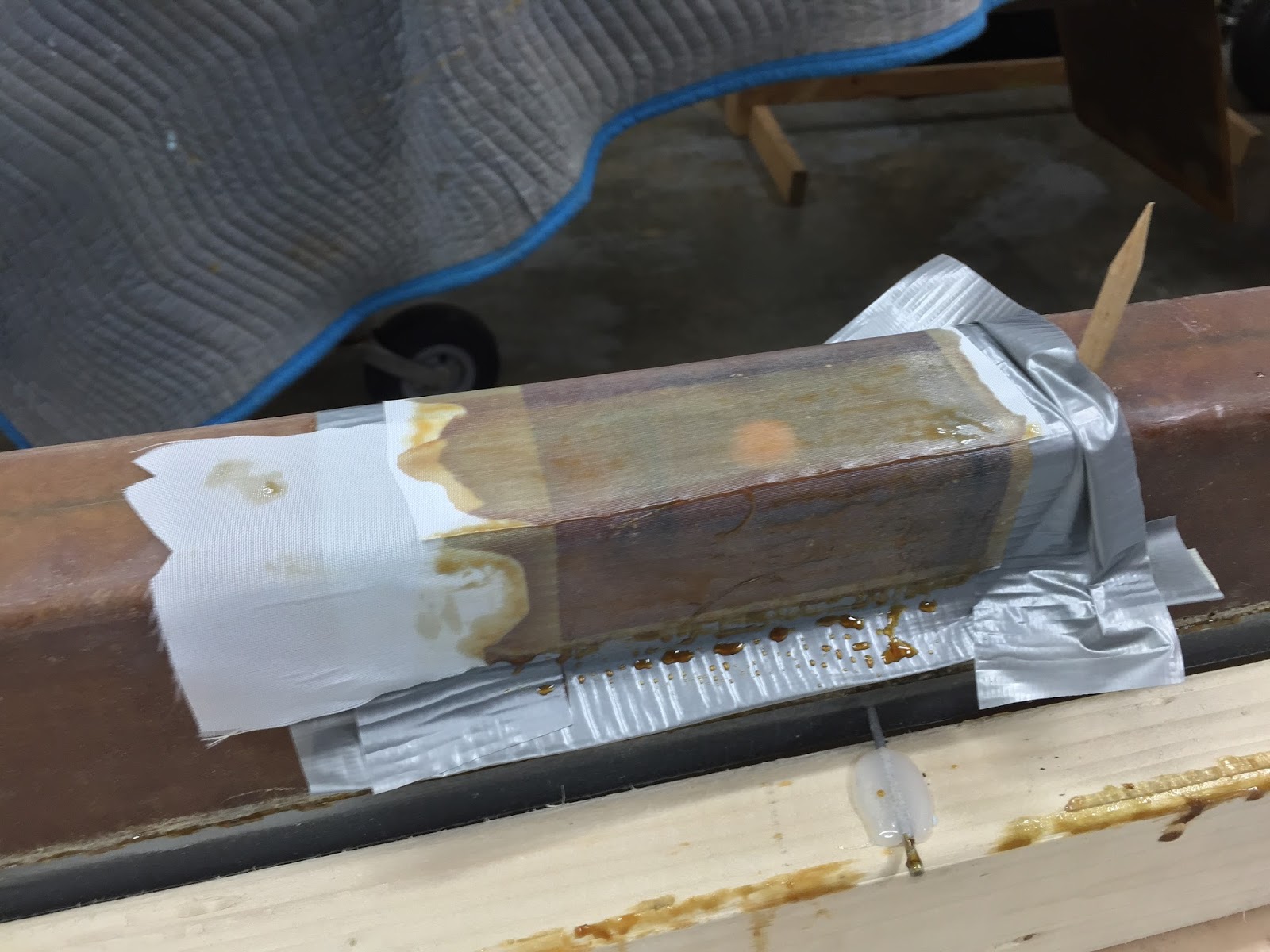
Putting Saran wrap into the CLI holes prevented epoxy from entering them while fiberglassing.
Saran wrap rolled into a cylinder filling one of the CLI holes
Saran wrap will be removed after fiberglassing
Talking about fiberglass, there was a lot of it to be cut, but with the table taken over by the canard and its jig, I had to move the fuselage outside so that I could cut the cloth on the floor.
I would suggest doing this on the big table before building the canard jig. Sigh!
Nine plies each will cover the CLI inserts
These 4x8 BID plies will be the last cover over the CLI inserts
Following my friend Wade’s lead, I pre-pregged all of the shear web fiberglass on the table, then transferred it to the foam cores.
Getting the plastic ready for pre-pregging
Micro-slurry being applied over the foam cores
Six layers of fiberglass stacked in the proper order covered with epoxy
Epoxy spread to all fiberglass while embedded within plastic sheets
Pre-pregged fiberglass being applied to the foam cores
Plastic removed, fiberglass smoothed out and air bubbles free (after a lot of work).
Lastly, I added the 9 BID plies over the CLI tabs, and a final 4"x8" ply of BID over those.
Nine 4"x1.5" BID plies (times two) to go over the CLI inserts.
I used flox instead of micro to smooth the 9 plies transition
Final ply going over the inserts
Shear web completed, or so I thought.
Lastly, I peel plied the whole thing and went to bed.
3" wide peel-ply going the long way is just perfect for this
The next morning, after removing the peel-ply I realized that I placed the last 4"x8" BID ply 90º off from the plans. Not knowing if this might become an issue, I decided to add another BID ply the right way this time, and just suck up the one day delay this would entail due to the cure cycle.
Note how the last BID ply goes all the way down to the bottom of the foam