With the excitement of multiple engine failures subsiding, it was time to settle in for the long haul. Up until this point, the amount of modifications I’d have to make was still unknown, but I had the sinking feeling that, however many I could imagine, there would always be a lot more I couldn’t even fathom.
 |
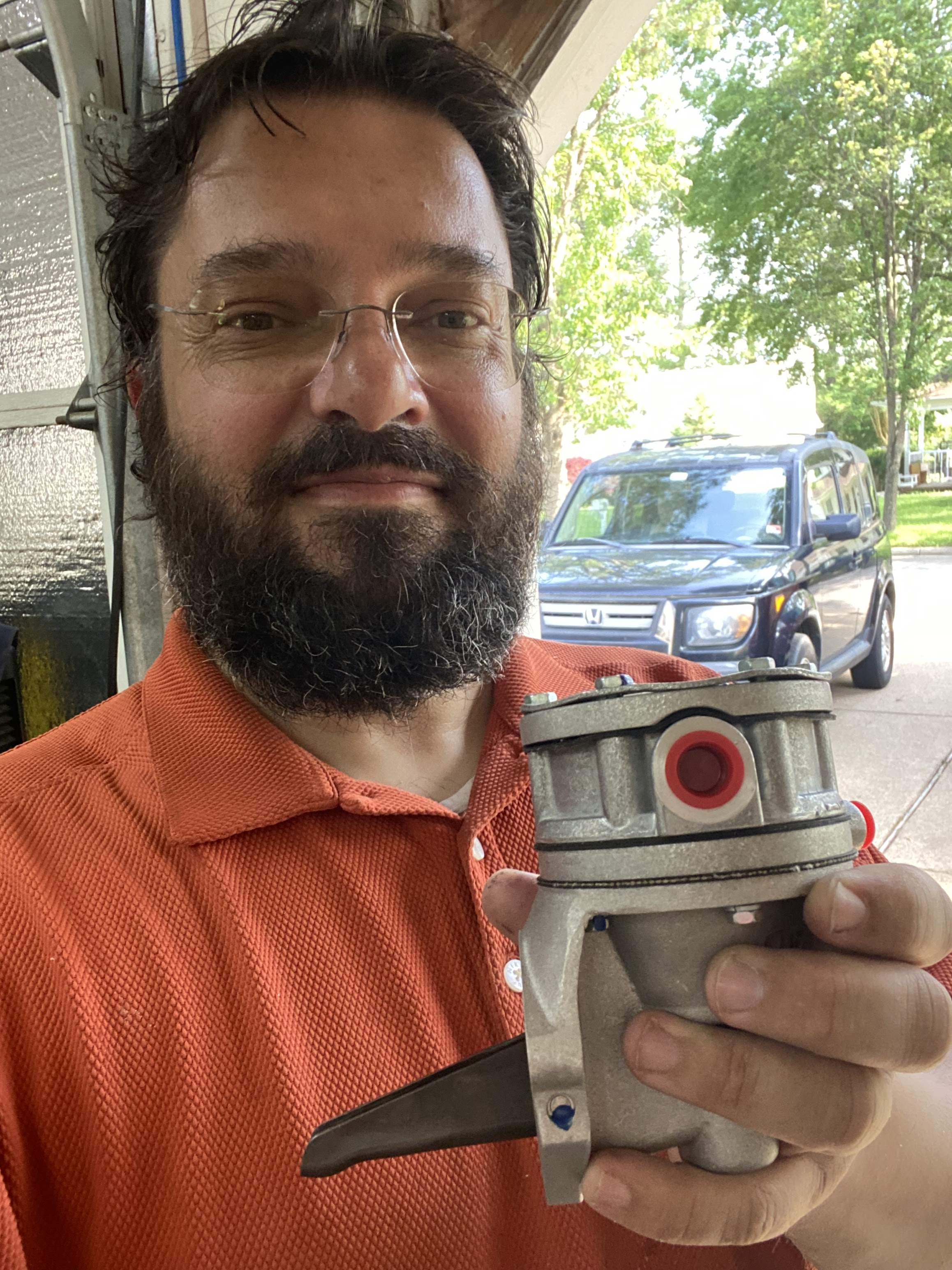
| The out-going Ellison Throttle Body Fuel Injector (aka Pressure Carburetor) |
Optimistically, I figured it might take four to six months of part time work between job related flying assignments. Little did I know that the effort to bring JT back from engine purgatory would end up stretching to 18 months of 10 hour days, 7 days a week, with no days off, but more interestingly, if we glance over the fear of the unknown, that I would enjoy every minute of it.
 |
| "Told ya it was gonna be fun!" |
When I started my own Long-EZ project (the one I haven’t finished yet) there were things about myself I didn’t know, and the act of building, year after year, brought to light much to my surprise. One being that, contrary to my natural disposition and probably induced by the epoxy's extremely long curing cycles, I can muster an other worldly amount of patience for certain things. Another being that as much as I enjoy flying, I get a deep sense of accomplishment from the act of building, even more so when there isn’t a clear plan to follow, like in this case. Sure, it is stressful, inefficient, and perhaps even dangerous, but creating something new from scratch is incredibly fulfilling, as close to giving birth as any man could ever come, I suppose.
As I mentioned last time, this is when the Covid pandemic began, and with my airline looking for volunteers to stay home at half pay in order to reduce the hemorrhaging of cash, I decided I’d help the both of us and get started on JT right away. First though, I had to come up with a general plan, and write down a list of all the modifications this would entail, a list that would no doubt continue to grow.
Luckily for me I had a couple of good examples of successful fuel injection installations to draw upon to create my own, Mike Beasley’s and James Redmond's, and one more in the works, Wade Parton’s. All of these had at least one thing in common, the type of fuel injection system, a Silver Hawk EX mechanical fuel injection servo by Precision Airmotive, basically a copy of the very successful Bendix unit made for experimental aircraft.
The only other option I could find was AirFlow Performance’s electronic fuel injection system, smaller and lighter than the Silver Hawk, but requiring electricity to operate, and the installation of a fuel return line to the tanks, both no-go items in my book.
With the SilverHawk ($$$$$) well recommended by trusted friends, I saw no need to look any further and put in an order for one, trusting that I’d figure out how to install it, eventually. The only thing that bothered me was that the fuel servo looked mighty big in the literature, and I wasn’t so sure it would fit inside JT's super-tight engine cowl.
To get a head start and help work out some of the fitting issues before the servo arrived, I decided to mock it up with a 3D printed facsimile, but to do this I first needed to create a CAD model (Computer Aided Design) to feed to the printer. Using the drawings from the downloadable SilverHawk installation manual, I imported each one in CAD, calibrated them to scale, and overlaid them on each of the 3 planes (XY, YZ, XZ).
 |
| Installation and detail specification EX-5VA1 Fuel Injection Servo |
 |
| 4 of the drawings from above in 3 dimensions |
Later, I used them to create a solid body with the right dimensions…
 |
| CAD solid body from the drawing projections in 3D |
 |
| Critical outside and inside dimensions were modeled accurately |
… and sent it to my 3D printer to get a usable substitute for the servo.
 |
| 24 hours of 3D printing later... |
 |
| Bolt patterns, throat sizes, and general outer dimensions were important. |
With the 3D servo in hand I was able to confirm that the SilverHawk unit was definitely much bigger than the Ellison.
 |
| The Silver Hawk is much taller and heavier than the Ellison |
This might have created interference issues with the existing cowling unless I got creative with its mounting, and given that this unit is orientation agnostic let’s look at a few options on how it could have been mounted...
1. Vertically, reusing the air filter box.
 |
| Original air filter installed with the 3D printed servo |
Although it was my preferred choice, this just didn’t fit, unless I wanted to put a hole through the bottom of the cowl, thus modifying the cowl's aft slope profile.
 |
| This double exposure showing the air filter box slightly protruding through the bottom cowl |
There are multiple reasons why this would have been a bad idea. Putting a bump in the cowl would require a more extreme change in the cowling up-slope profile (after the bump), possibly surpassing the maximum 7º angle of airflow direction change that resists airflow separation. Airflow separation introduces areas of reversed flow (much like a stalled wing), and increases drag dramatically. Moreover, airflow separation in front of the propeller reduces propeller efficiency, and might create vibrations due to the turbulent airflow fed to the propeller as each blade flies in and out of the disturbed air in the lower half of its travel. So, any sharp cowling surface change of more than 7º increases drag and reduces thrust.
Just in case those were not reasons enough, putting a hole through the bottom of the cowling would go against my #1 axiom of not needing to repaint JT.
2. A horizontal mount with one 90º adapter.
 |
| The different colors were from leftover spools of ABS |
 |
| This is compact, I like it. |
 |
| Can you spot the multiple issues here? |
This mounting was not bad at all, but it came to within 0.5” of the NACA diffuser and 5.5” from the firewall. Not sure how I’d put an air filter there, but the NACA diffuser would need to get cut for sure. This type of surgery, while technically violating my #1 axiom, would do so in an area not visible unless the cowling was removed.
Hmmm... don't think I'm ready to commit yet.
3. An extension, and a horizontal mount as before.
 |
| Might have to machine something like this out of aluminum |
 |
| This is starting to get complicated |
 |
| Well, that seems to fit better already. |
I liked this much better, but it would still put the end of the servo too close to the NACA Diffuser which would still end up getting cut in order to install some kind of air filter.
 |
| Dang! This is still too close. |
So, not a big improvement. The cons would be I’d have to machine the extension myself from billet, and the heavy servo would be hanging further and further from the mounting point, increasing possible vibration related issues, and needing some kind of bracing. Also, the air filter would end up protruding into the NACA, possibly creating havoc with the delivery and distribution of cooling air to the engine, as this is a critical area of a NACA duct that must be clear and smooth in order to corral air particles into its throat.
 |
| Very nice alignment with the airflow though |
Filter selection would be also be very difficult, if not impossible, due to the new diameter constraint introduced by the NACA entry dimensions.
 |
| Where the heck am I going to find an air filter to fit this narrow gap?! |
4. The triple bend.
 |
| This is getting a bit ridiculous, and expensive. |
I know, it’s starting to look a bit crazy, but one has to explore all options, right?!
On one hand this still has all of the vibration related issues of the former, adds $300 worth of elbows, but increases the space available to add an air filter, and it is still in line with the incoming airflow through the NACA duct.
 |
| All the headroom I always wanted |
Unfortunately the cowling cannot be closed in this configuration, and we are back to the hole in the cowl scenario, though not as bad as before.
 |
| The light way in the back indicates the cowl is not closing |
 |
| Can you see the issue? |
5. Going the other way.
 |
| Perhaps using some flexible SCAT tubing... |
This didn’t really go anywhere fast, but I had to try.
6. Coming in from the rear 😉
This would require replacing the oil pan with one that has the air passage in the back (front, in a tractor engine) instead of the bottom.
 |
| The extender/90º/90º version. |
 |
| The 90º/extender/90º version. |
Wade Parton is doing a version of this, but his cold air induction system is $3000 if I remember correctly, and my cowling still wouldn’t fit properly in the rear.
I might have played with a few more variations, but you get the picture. Of all the different ways to skin this cat, only one allowed me to not cut the cowling… Option #2. Yes, I’d have to cut the NACA Diffuser to fit an air filter, but I would kick that can down the road for later.
Meanwhile, talking to my friend Mike Beasley, I found out that he actually used this installation method paired with a K&N RC-9700 air filter, and has close to a full inch of clearance from the firewall.
 |
| K&N RC-9700 |
Are you thinking what I’m thinking?
Yes! I decided on Option #2, secretly hoping that our engine mounts would be similar enough to also grant me the 1” spacing from the firewall I needed, and just as I was making this all important decision, Santa... I mean, UPS showed up with a bunch of presents.
 |
| What could it be?!🤔 |
 |
| There's a nice high pressure mechanical fuel pump! |
 |
| And a Silver Hawk fuel servo with a side of EFII recirculating high pressure electric fuel pump |
 |
| The 3D printed unit turned out to be a great substitute |
But that’s enough decisions for one post. Join me again next time, and I’ll tell you all about these fuel pumps, and the extensive modifications to the fuel system.