Disclaimer

This blog is for entertainment purposes only, and is not meant to teach you how to build anything. The author is not responsible for any accident, injury, or loss that occurs as a result of reading this blog. Read this blog at your own risk.

Thursday, December 17, 2020

JT’s miscellaneous updates #2

While JT was in my garage last winter, I made many small updates to various systems. Today we are going to take a look at a few of them that do not warrant their own post.


Pitot-Static redo


One amusing thing that happens when flying formation with BizMan and Chris is that Mike's airspeed indicates roughly 5 knots faster than mine, and Chris' about 10. 


Not knowing who’s indication is correct, I decided to do over JT’s entire Pitot-Static system using all new modern air lines and connectors, thus replacing all possible leak initiators including several feet of mismatching tubes, adapters, and homemade plugs.


Complete lack of standardization among Pitot/Static hoses

Making a more direct path for the dynamic pressure hose


I decided to start up front at the Pitot inlet by removing the initial run of tubing, and replacing it with the softer one that came with my Trig’s ADSB. This softer tube helped me bridge between the aluminum Pitot tube and the modern 1/4″ Nylon lines.


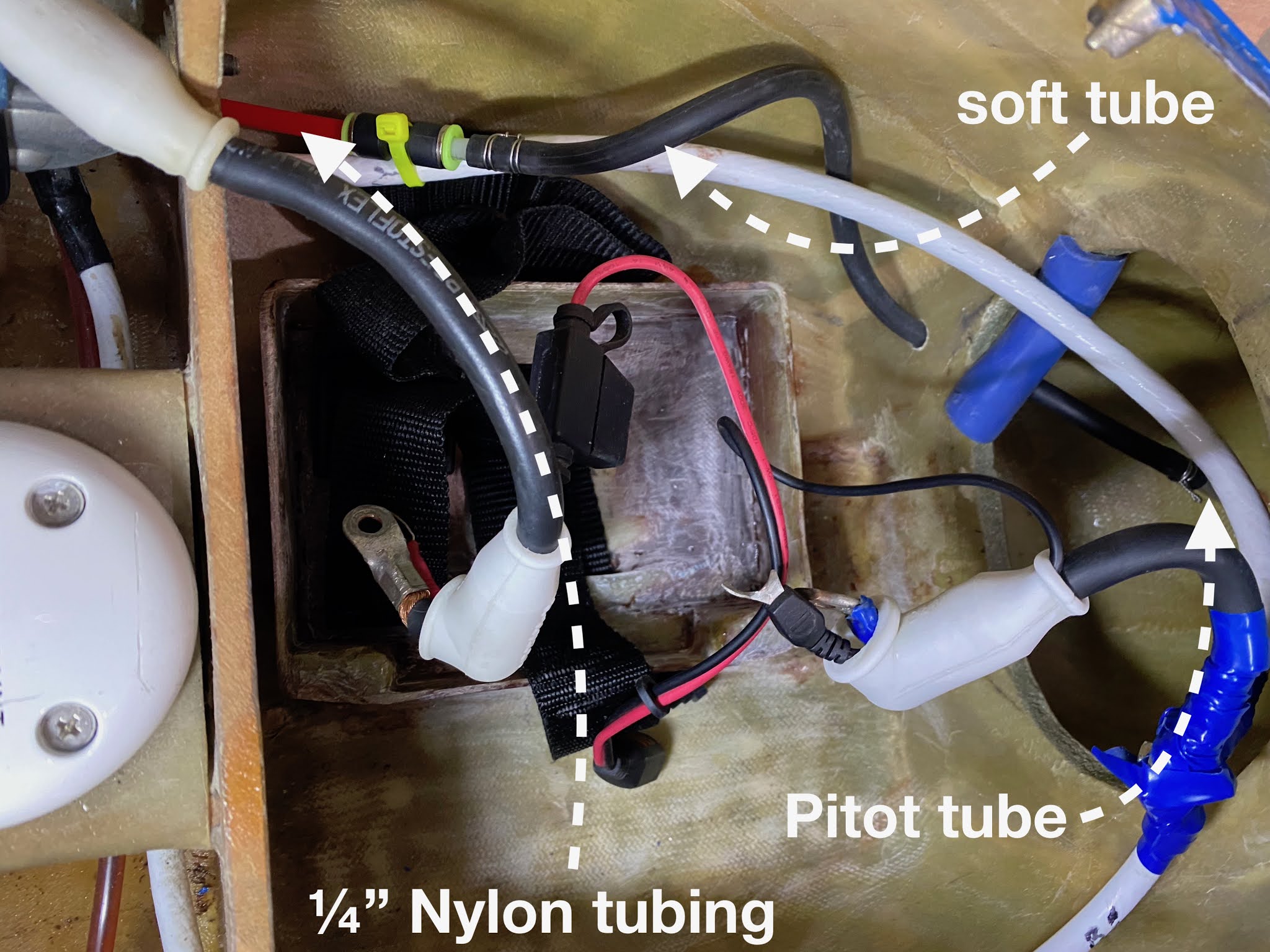
Soft rubber tube between aluminum Pitot tube and 1/4" nylon line


Further back in JT’s nose I decided it would be easier to rip everything out and start over again.


1/4" tubing and proper manifolds used throughout


Pressure tubes come to an end right in front of the instrument panel (behind actually)

One thing I did to simplify my life in the future is splitting the “alternate static” tube, and adding an extra line that will be used to tie into the Pitot-Static system at inspection time. This tube will remain neatly tucked under the front seat, and easily deployed when needed.


Added a way to check the Pitot/Static system from under the  front seat


Back from the future (Dec 2020)… I just had the Pitot/Static and Transponder inspected, and they were spot on, so all the rework turned out well.


Panel painting


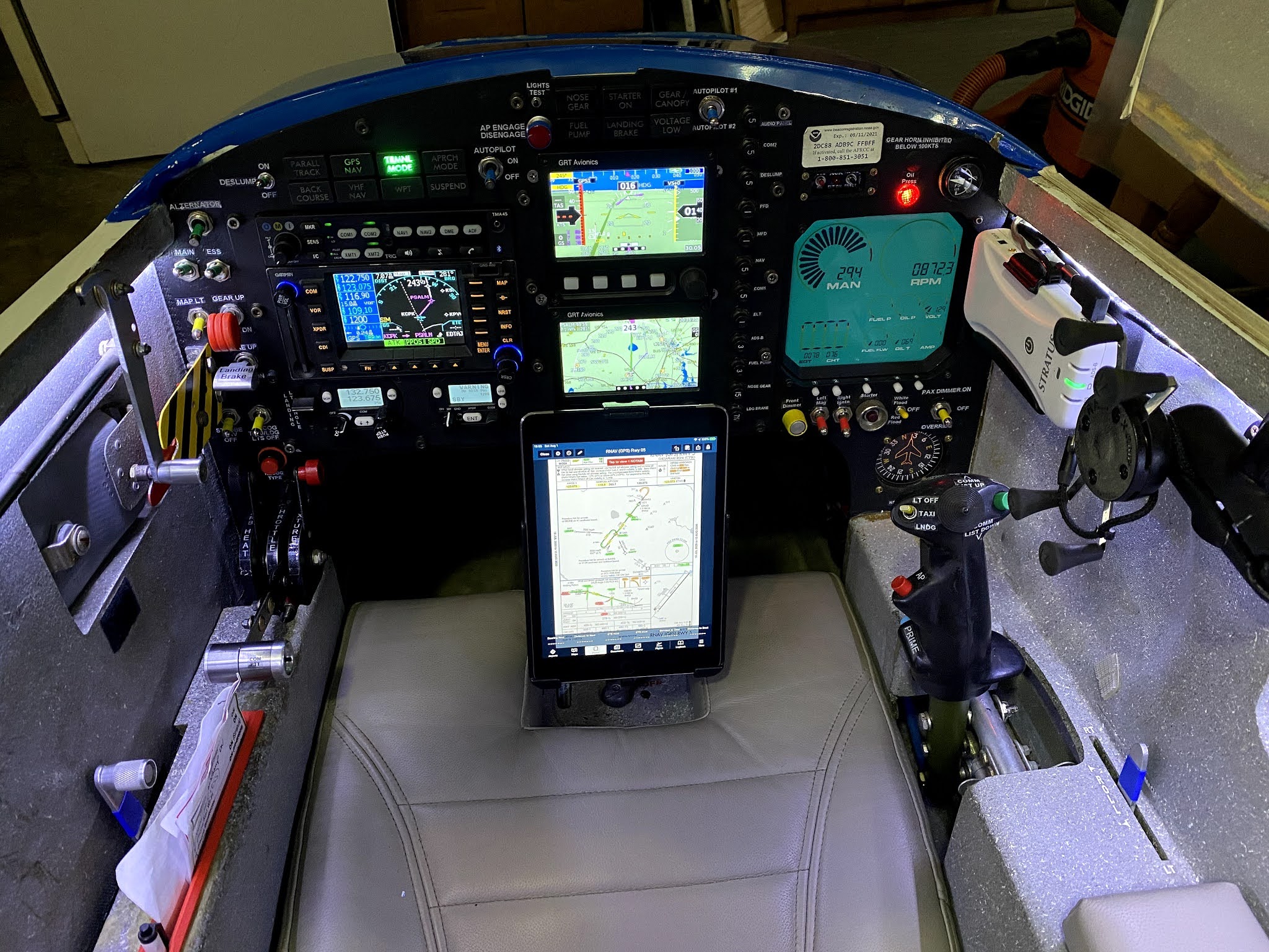
After nearly two decades in service, and numerous instrument updates, the gray instrument panel looked a bit worse for wear.


Well broken-in panel


So, while the panel was still apart, I took the opportunity to rattle-can a matte black coating of paint on the fiberglass skeleton, matching the color of the new metal instrument panel, thus tying all instrumentation together visually into a more cohesive unit. 


Not taking any chances with the black paint


Masking is the key to not screwing it up

A couple of coats of primer...

... then a few coats of black paint.

"It'll eat!"

Definitely!
 

Latch makeover


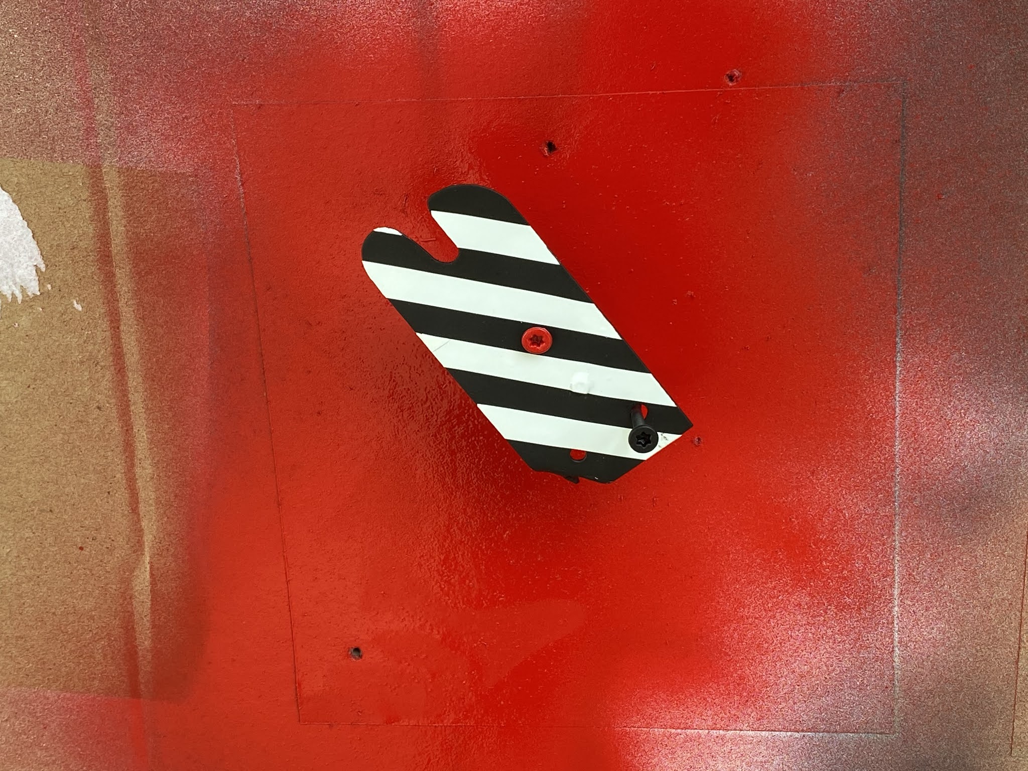
There was nothing inherently wrong with the canopy latching system, but its white color looked a little worn. 


Back side of canopy latch (upside down)


I figured that while I was still in painting mode I would touch up the latch as well. 


Having ridden on four different ejection seat systems in my distant past, I decided to use the ejection handle colors as an inspiration to highlight the way to get out of JT.


Highly contrasting, not naturally occurring color combination. Perfect!

Adding white tape to the now black latch before painting it yellow

My spray booth

Yellow over black latch, with a red movable locking tab.

Hard to miss when it's time to get out


Essential Bus beef up


JT used to have two semi independent electrical busses. All important electrical loads were connected to the Essential bus, the rest to the Main bus.


Because the busses were tied together through a diode rectifier bridge, turning on the Main bus would also connect all of the items on the Essential bus (not true the other way around). In case of alternator failure one could shed unimportant items by switching ON the Essential bus before switching OFF the Main bus, and running the battery down while looking for a place to land.


This worked very well with a VFR panel. Unfortunately, adding IFR capabilities meant that more new radios became essential to safety, and had to be placed on the Essential bus, as one wouldn’t want to lose the ability to fly an instrument approach, for example, due to an alternator failure.


This electrical scheme worked well up to panel #3, but by panel #4 the load on the Essential bus was becoming too high, and I would have occasional brownouts where the Garmin GNS480 would go black for a minute or two, then start back up. This was of course a major problem, and stopped all IFR flying until I could understand this issue, and fix it.


My biggest problem was that this issue seemed totally random and impossible to reproduce on the ground, thus it didn’t lend itself to being easily diagnosed. 


Eventually, I did stumble on the curious fact that the Essential bus voltage was about 1.5V less than the Main bus after being powered for a few hours, but only about 0.5V less at the beginning of my testing. Also the bridge rectifier felt very hot after running that long.


Strangely, when I also flipped ON the Essential bus switch, both busses had the same exact voltage, and the bridge rectifier cooled down.


You might have recognized the issue already, but if you didn’t, let me explain what was happening. 


Increasing the loads on the Essential bus side flowed much more current through the bridge rectifier in the IFR configuration than it did in its VFR days. With the bridge rectifier operating right against its rated current limits, the 0.5 volt initial drop due to the diodes, tripled as the heat built up, causing a brownout of the biggest load in the panel, the Garmin GPS/COM/NAV (10 continuous amps). With the load reduced by the brownout, the diode bridge rectifier would cool down. With its ability to flow more current restored, the Garmin device would start up again.


Powering the Essential bus via its own switch bypassed the rectifier by connecting the bus directly to the battery, in a similar way to the Main bus, hence the equal voltage, and the cool diode bridge.


The solution for the short term was keeping the busses electrically independent by turning ON both the Essential and Main switches for flight. After a period of flying in that configuration with no further issues, I removed the bridge rectifier altogether thus separating forever the two busses. 


My checklist now calls for both switches to be turned on initially, and the Main bus to be turned OFF in case of alternator failure, thus shedding those unneeded loads.


With the list of necessary items being added to the Essential bus growing, an ever increasing amount of current started flowing through the Essential bus switch so, in an effort to relieve the switch and its wiring from all this electrical load, I decided to add a relay to the Essential bus. 


JD2912-1H-12VDC 80A 14VDC


The relay was cheap, light, easy to mount, and has worked flawlessly ever since.


87 grams including the connector (didn't use it)

Diode prevents voltage spike of a collapsing magnetic field from eroding the switch contacts

Left side of the nose is "Relay City"


With this latest electrical modification here's what JT’s main electrical system looks like…


JT's latest wiring scheme


Friday, November 27, 2020

Shop preparation - Part 8

Transformer table


Of all the things I had to build to get this project going, the one I am most proud of is the big table, I just wouldn’t have been able to get much done without it.


Besides being level in all directions, which came in handy many a time, one cool thing about it is that I have been able to modify it to suit my evolving needs as new challenges present themselves.


"I'm calling it good enough!"


The first table modification occurred when I was trying to mount the main landing gear on the upside down fuselage. Remember the “Straight Tower of Pisa” mod? 


Table modded to help mount the main gear bow

Now that the right wing is mounted to the table, I find myself once again wanting to reinvent it in order to make my life easier. 


The newest addition to the table is a temporary extension that will allow me to pre-preg the entire shear-web at once.


I will be taking this extension down after glassing the sheer-web


The versatility of this table is truly amazing, the only limiting factor being my imagination, but rest assured there are plenty of crazy ideas where the previous ones came from, so I should be able to make you scratch your head for years to come.


Case in point, my latest table add on.


You see, with the wing on the table ready for glassing the sheer-web, I realized that as it sits, I am not tall enough to do the kind of quality work I want to be able to do on some portions of the wing, namely the tallest portion and the back side of it. 


Normally the table is at the perfect height. This time I wished it was lower.


Sure, I could be standing on a stool, and I did practiced with it, but spending a few minutes on a step stool is very different than standing on it, for hours fiberglassing. My reach is limited, and rather than climbing down, repositioning, and climbing back up a thousand times, my tendency would be to stretch how far I can push it, and either fall off of the stool, or do poor quality work on the back side of the wing, or both.


I thought about making a multilevel bench that followed the raising wing section along the table, but I had a more original idea… 


How about removable floating scaffolding?


What does that even mean? You say.


Think about the top platforms of a multilevel bench, and imagine it floating in space without any apparent support, yet attached to the table. 


Now that’s something worth cutting some 2x4 for!


Yet, you might wonder… Would it be able to take the weight?


To which I have to reply by asking… How much weight does it take to snap a sideway 2x4? 


Hmmmm, not sure exactly, but most U.S. building codes allow for a 24” cantilever. 


Definitely way more than I need, but I’ll take it.


Time to start cutting!


The table was already spoken for, so I had to improvise.

The special ingredient in my design was to not rely on any screws for support, but to leverage the existing structure of the table to hold up the platforms, and use screws only for maintaining things in the proper position. 


I added 2x4 sections in strategic locations for this purpose.


This is the secret sauce

As a matter of fact, these platforms could, and did hold my weight without needing any screws at all, but I wouldn’t trust that structure to be stable enough to be safe.


Platform support beam captured by the 2x4 added to the table legs.

Framework in place

"Look Ma', no screws!"

Pretty cool, uh?!


Finally, I trimmed the support studs and the plywood, and added a few screws to make sure that the support beams didn’t slip off the makeshift channels.


Fiberglassing the EZ way 😂

Removing the platforms is as easy as removing eight screws, and sliding them out.


So, here’s how I envision using this floating scaffolding to help me fiberglass the shear-web…


Testing the scaffolding


Overly complex, you say?


I do not disagree, but it was a ton of fun to come up with and to make, and when a project spans over a decade, anything that keeps things interesting and the creative juices flowing is a much welcomed development. 


The jury is still out on how the scaffolding will perform under pressure (pun intended), but we are about to find out very soon.


Tuesday, November 24, 2020

Ch 19 - Wings and ailerons - Part 2

Wing attachment points (45.0 hrs)


"How many bolts does it take to mount a Long EZ wing to the fuselage?"


"Three."


Yep, you read it right, only three bolts are needed to keep each wing attached to the center-section spar, and the wing bolts attachment points (aka metal plates) are all installed in the first foam block (FC1).


Eureka CNC plans broken down by major foam blocks

Two of these bolts are accessed through two small dedicated depressions cut into the top and bottom of the wing, and one from the wing root pocket.


Using JT to illustrate the location of the wing's top bolt...

... and the wing's bottom and inner bolts

The plans will have you do the work of creating these pockets with the foam blocks already in the jig, but it is much easier to do it before glueing FC1 to the rest of the wing.


Let’s work on the root pocket first, then we’ll do the other two.


This process involves slicing off a part of FC1, hollowing it out, then glueing it back to FC1, then installing the first one of many metal plates.


Marking the cut line on the wing root foam block

Using two nails on the black line as guides for the ruler

Clamped one ruler on the wing foam top, and another one on the wing foam bottom.

Using the rulers as guides for the saw

This will become the wing root pocket

Using the rulers as guides again

Cutting off the critical 0.6" (15 mm) dimension

Front face to be reattached later, 0.6" non-critical perimeter marked in black.

Creating the wing root cavity

The inner piece of foam will be reused to stabilize the now delicate foam perimeter

Front face reattached to the perimeter foam, curing around the inner core 

Wing root section with micro, in preparation for getting reattached to FC1 foam block.

Wing root section curing after being reattached to FC1

Talking about metal plates, I had already made most of them years ago when I was working on the center-section spar, but a few of them weren’t mentioned in the spar chapter, so I had to make some new ones.


Two LWA4 ¼" (6.35 mm) 2024 Al plates, and two WI8 0.016" (0.4 mm) 2024Al sheet 

Etched then Alodined the metal parts

My Alodine is a bit weak, so I used aviation style etching primer on the plates

We will use these a little bit later. First we have to create the depressions for the outer two wing bolts, one on top of the wing, the other on the bottom, then glass them.


I often colorize the plans' photos in the blog to make them a little easier to understand


Unfortunately the depth of the two depressions are not only different, but also decreasing the further back one goes due to the slant of the wing profile. 


Measuring the deepest part of the slot (gray= metal, blue = foam)

Bottom slot is 0.030" (0.76 mm) shallower


The floor of the depression however is perpendicular to the front face of the foam block, so with a little ingenuity (thanks Ary) it is possible to cut the foam as in the plans.


Drawing dimensions on foam is difficult. I learned this trick from Walter Grantz (R.I.P. my dear friend).

It's just regular painter's tape, nothing fancy, but the pen marks are much more readable.

Bottom slot dimensions marked

Establishing a reference plane (plexiglass) perpendicular to the front face of the foam 

Using the reference plane as an aid to cut the slot to the charted depth

This was Ary's idea, and worked quite well.

The obligatory photograph for a future DAR (Designated Airworthiness Representative)

Slow progress precision foam removal

Here's a perfect variable depth slot perpendicular to the foam face

Shimming the square to establish the reference plane on the opposite side

Bottom slot cut using the same technique

Wow, that was a little bit weird, but worked quite well. Time to glass the pockets.


I think I use as much duct tape as I do fiberglass building this plane

Two plies of BID cut at 45º bias

Foam slurried, and micro fillet applied to the edges.

BID prepregged

BID applied and peel-plied

Always use a bigger piece of glass than needed, then trim later.

What a difference a day makes!

Slot trimmed and lightly sanded to remove all peel-ply strands

Most of you probably already know what’s going on here, but for those new to fiberglassing let’s look at this process again in detail on the bottom side of the wing.


FC1 flipped over to repeat the process on the bottom slot

One can never have too much duct tape

Painting on the micro-slurry

Wetting the BID cloth with pure epoxy in between plastic sheets

The result is what we call pre-preg

Pre-preg means previously impregnated, referring to a ready-to-use epoxy soaked fiberglass sheet.

Pre-preg is easier and less messy to work with. Just peel the backing plastic, and stick where needed.

Then one works it down to the foam with an epoxy soaked brush

Peel-ply added over the fiberglass (not required in this instance)

The glass should have lapped slightly over the metal plates, but I chose to install them later.

Peel-ply removal time

Cleanup is alway a bit tedious

Bottom slot ready for business

I like the way those pockets came out. Now we just need to recess them, and the foam, so that we can fit the metal plates through which the wing bolts will connect to the main spar.


The two metal plates I should have mounted before glassing the slots

Setting the Dremel tool to a depth equal to the thickness of the LWA4

Ready to remove material

Foam and glass removed to accommodate the LWA4 plate

Test fitting the bottom LWA4

LWA4s need to be flush with the foam as they will be glassed over by the shear-web

The plate didn’t line up exactly the way I would have liked, so I used toothpicks to hold it in place for the next step.


Creating a flox corner by removing foam, and sanding the micro-slurry off the back of the glass.

Using toothpicks to make up for my previous lack of control with the Dremel tool

The toothpick trick worked amazingly well in lining up LWA4 precisely

Flox in the corner (hence the flox-corner name)

LWA4 and WI8 floxed to the slot

In case you were wondering, I did not remove the toothpicks. There was really no need to do so, as the toothpick are stronger than the foam they displace anyway.


You might notice I used flox instead of micro here. I did this for two reasons. First, I wanted to create a flox corner between the fiberglass of the slot, and the fiberglass of the shear-web that will go over it (and the metal plates). Second, since I didn't lap the fiberglass slightly up the metal plate in the pocket (as seen in section B-B on page 19-12), a little extra strength there made me feel better. Probably not necessary, but definitely didn’t hurt anything.


The toothpick trick worked well by the way, and the plates lined up with the foam surface correctly.


The next day I double-checked for alignment with the foam

The toothpicks certainly worked their magic

Getting three surfaces to align at the same time can be a challenge

This might be a good point to bring up a Builder Hint from CP38…


JT doesn't have this, and I haven't had any issues to date, but #2 will get this soon.


I’ll put that off until later. For now let’s concentrate on the top pocket using the same toothpick trick to line the metal plates up with the foam.


More targeted toothpick action

Flox will close the slight gap

Taped the two plates together

Test fitting the plates together

Duct tape means we are ready for business

Floxing the corner

Adding the metal plates

Using some small tools to add weight to WI8 while curing


Last but not least is the inboard wing mount.


Test fitting LWA6

Duct tape to the rescue!

One last check after priming

I used micro here since it will mostly be removed while glassing the wing root pocket at a later date.


Micro used here

LWA6 curing

Next day. LWA6 is there to stay.

Nothing left to do but bond FC1 to the rest of the aft wing already in the jig.


Just as with the rest of the foam blocks, slurry and wet micro will glue them together.

FC1 reunited with the rest of the aft wing in the jig

The ever present duct tape

I used nails as usual to hold things steady while curing

One day later we are back in business, ready to begin work on the shear-web.


Stay tuned, because next time we will begin the process of building the internal structural parts of the right wing.