While JT was in my garage last winter, I made many small updates to various systems. Today we are going to take a look at a few of them that do not warrant their own post.
Pitot-Static redo
One amusing thing that happens when flying formation with BizMan and Chris is that Mike's airspeed indicates roughly 5 knots faster than mine, and Chris' about 10.
Not knowing who’s indication is correct, I decided to do over JT’s entire Pitot-Static system using all new modern air lines and connectors, thus replacing all possible leak initiators including several feet of mismatching tubes, adapters, and homemade plugs.
 |
| Complete lack of standardization among Pitot/Static hoses |
 |
| Making a more direct path for the dynamic pressure hose |
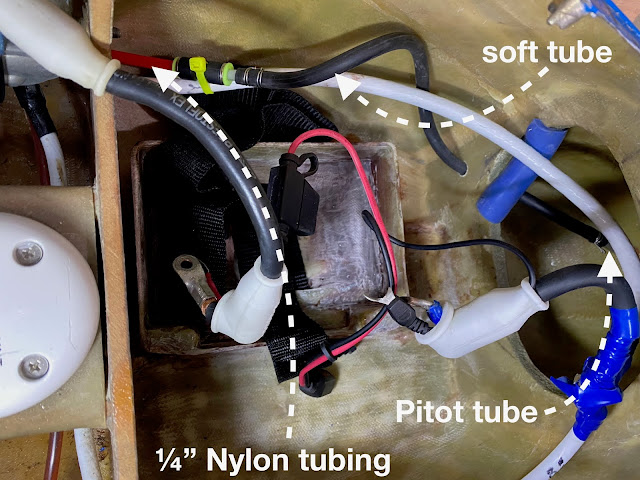
I decided to start up front at the Pitot inlet by removing the initial run of tubing, and replacing it with the softer one that came with my Trig’s ADSB. This softer tube helped me bridge between the aluminum Pitot tube and the modern 1/4″ Nylon lines.
 |
| Soft rubber tube between aluminum Pitot tube and 1/4" nylon line |
Further back in JT’s nose I decided it would be easier to rip everything out and start over again.
 |
| 1/4" tubing and proper manifolds used throughout |

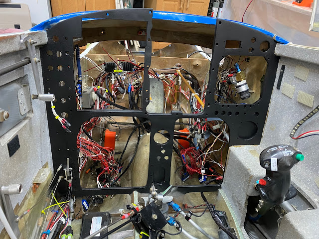
Pressure tubes come to an end right in front of the instrument panel (behind actually)
One thing I did to simplify my life in the future is splitting the “alternate static” tube, and adding an extra line that will be used to tie into the Pitot-Static system at inspection time. This tube will remain neatly tucked under the front seat, and easily deployed when needed.
 |
| Added a way to check the Pitot/Static system from under the front seat |
Back from the future (Dec 2020)… I just had the Pitot/Static and Transponder inspected, and they were spot on, so all the rework turned out well.
Panel painting
After nearly two decades in service, and numerous instrument updates, the gray instrument panel looked a bit worse for wear.
 |
| Well broken-in panel |
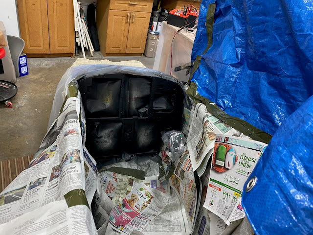
So, while the panel was still apart, I took the opportunity to rattle-can a matte black coating of paint on the fiberglass skeleton, matching the color of the new metal instrument panel, thus tying all instrumentation together visually into a more cohesive unit.
 |
| Not taking any chances with the black paint |
 |
| Masking is the key to not screwing it up |
 |
| A couple of coats of primer... |
 |
| ... then a few coats of black paint. |
 |
| "It'll eat!" |
 |
| Definitely! |
Latch makeover
There was nothing inherently wrong with the canopy latching system, but its white color looked a little worn.
 |
| Back side of canopy latch (upside down) |
I figured that while I was still in painting mode I would touch up the latch as well.
Having ridden on four different ejection seat systems in my distant past, I decided to use the ejection handle colors as an inspiration to highlight the way to get out of JT.
 |
| Highly contrasting, not naturally occurring color combination. Perfect! |
 |
| Adding white tape to the now black latch before painting it yellow |
 |
| My spray booth |
 |
| Yellow over black latch, with a red movable locking tab. |
 |
| Hard to miss when it's time to get out |
Essential Bus beef up
JT used to have two semi independent electrical busses. All important electrical loads were connected to the Essential bus, the rest to the Main bus.
Because the busses were tied together through a diode rectifier bridge, turning on the Main bus would also connect all of the items on the Essential bus (not true the other way around). In case of alternator failure one could shed unimportant items by switching ON the Essential bus before switching OFF the Main bus, and running the battery down while looking for a place to land.
This worked very well with a VFR panel. Unfortunately, adding IFR capabilities meant that more new radios became essential to safety, and had to be placed on the Essential bus, as one wouldn’t want to lose the ability to fly an instrument approach, for example, due to an alternator failure.
This electrical scheme worked well up to panel #3, but by panel #4 the load on the Essential bus was becoming too high, and I would have occasional brownouts where the Garmin GNS480 would go black for a minute or two, then start back up. This was of course a major problem, and stopped all IFR flying until I could understand this issue, and fix it.
My biggest problem was that this issue seemed totally random and impossible to reproduce on the ground, thus it didn’t lend itself to being easily diagnosed.
Eventually, I did stumble on the curious fact that the Essential bus voltage was about 1.5V less than the Main bus after being powered for a few hours, but only about 0.5V less at the beginning of my testing. Also the bridge rectifier felt very hot after running that long.
Strangely, when I also flipped ON the Essential bus switch, both busses had the same exact voltage, and the bridge rectifier cooled down.
You might have recognized the issue already, but if you didn’t, let me explain what was happening.
Increasing the loads on the Essential bus side flowed much more current through the bridge rectifier in the IFR configuration than it did in its VFR days. With the bridge rectifier operating right against its rated current limits, the 0.5 volt initial drop due to the diodes, tripled as the heat built up, causing a brownout of the biggest load in the panel, the Garmin GPS/COM/NAV (10 continuous amps). With the load reduced by the brownout, the diode bridge rectifier would cool down. With its ability to flow more current restored, the Garmin device would start up again.
Powering the Essential bus via its own switch bypassed the rectifier by connecting the bus directly to the battery, in a similar way to the Main bus, hence the equal voltage, and the cool diode bridge.
The solution for the short term was keeping the busses electrically independent by turning ON both the Essential and Main switches for flight. After a period of flying in that configuration with no further issues, I removed the bridge rectifier altogether thus separating forever the two busses.
My checklist now calls for both switches to be turned on initially, and the Main bus to be turned OFF in case of alternator failure, thus shedding those unneeded loads.
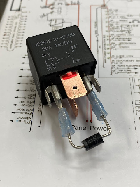
With the list of necessary items being added to the Essential bus growing, an ever increasing amount of current started flowing through the Essential bus switch so, in an effort to relieve the switch and its wiring from all this electrical load, I decided to add a relay to the Essential bus.
 |
JD2912-1H-12VDC 80A 14VDC |
The relay was cheap, light, easy to mount, and has worked flawlessly ever since.
 |
| 87 grams including the connector (didn't use it) |
 |
| Diode prevents voltage spike of a collapsing magnetic field from eroding the switch contacts |
 |
| Left side of the nose is "Relay City" |
With this latest electrical modification here's what JT’s main electrical system looks like…
 | |
| JT's latest wiring scheme |
Awesome work Marco!
ReplyDeleteThanks Mike.
DeleteSweet! My most favorite part was the line, "...when flying formation with BizMan and Chris.." :-)
ReplyDeleteHa ha! I knew you would.
Delete