This is gonna require a little explaining…
The Center Section spar (CS spar) is a hollow forward facing C-shaped structural member with lighter fiberglass coverings enclosing the front of the C, and both ends.
 |
| CS spar/wing junction |
The wings are attached to the fuselage CS spar with three bolts, one close to the engine, and two further outboard. Each bolt is driven forward through a hole in the wing, then into a corresponding hole into the CS spar.
 |
CS spar bolt holes
|
The nuts that engage with the two outer bolts must be inserted into the CS spar from a small hole below the spar. It takes at least a team of two to tighten them.
 |
| My finished CS spar with various holes |
The inner nuts require someone to sit in the passenger seat and stick an arm into the CS spar up to his shoulder with a wrench, then blindly feel backward for the bolt, use the one hand to thread the nut onto the bolt, and use the wrench to hang on to the nut while someone else from outside cranks on the bolt. This is a pain in the rear, but not nearly as bad as the two outer nuts.
 |
| Tightening the CS spar inner bolt |
Tightening nuts on the outer bolts is a very difficult process in my experience, and the smaller the hole the builder cut into the bottom of the CS spar, the harder it is to deal with them. The top bolt can barely be seen inside the CS spar, but it is not easily reached with a tool, while the bottom bolt can be more easily reached, but not seen at all.
Let it be said that mounting the wing even once is enough to make you never want to take it off again.
Enter the “Reverse Bolts” mod.
The main idea is to have the bolts backward from inside the spar, and mount the nuts on the outside.
How is this any better?
Well, the key to this modification is to mount a U channel inside the spar that captures the head of the bolts and prevents them from backing out when mounting the wing, and from rotating when tightening the nuts outside. To this last point, the fit of the U channel over the bolt head must be as tight as possible.
 |
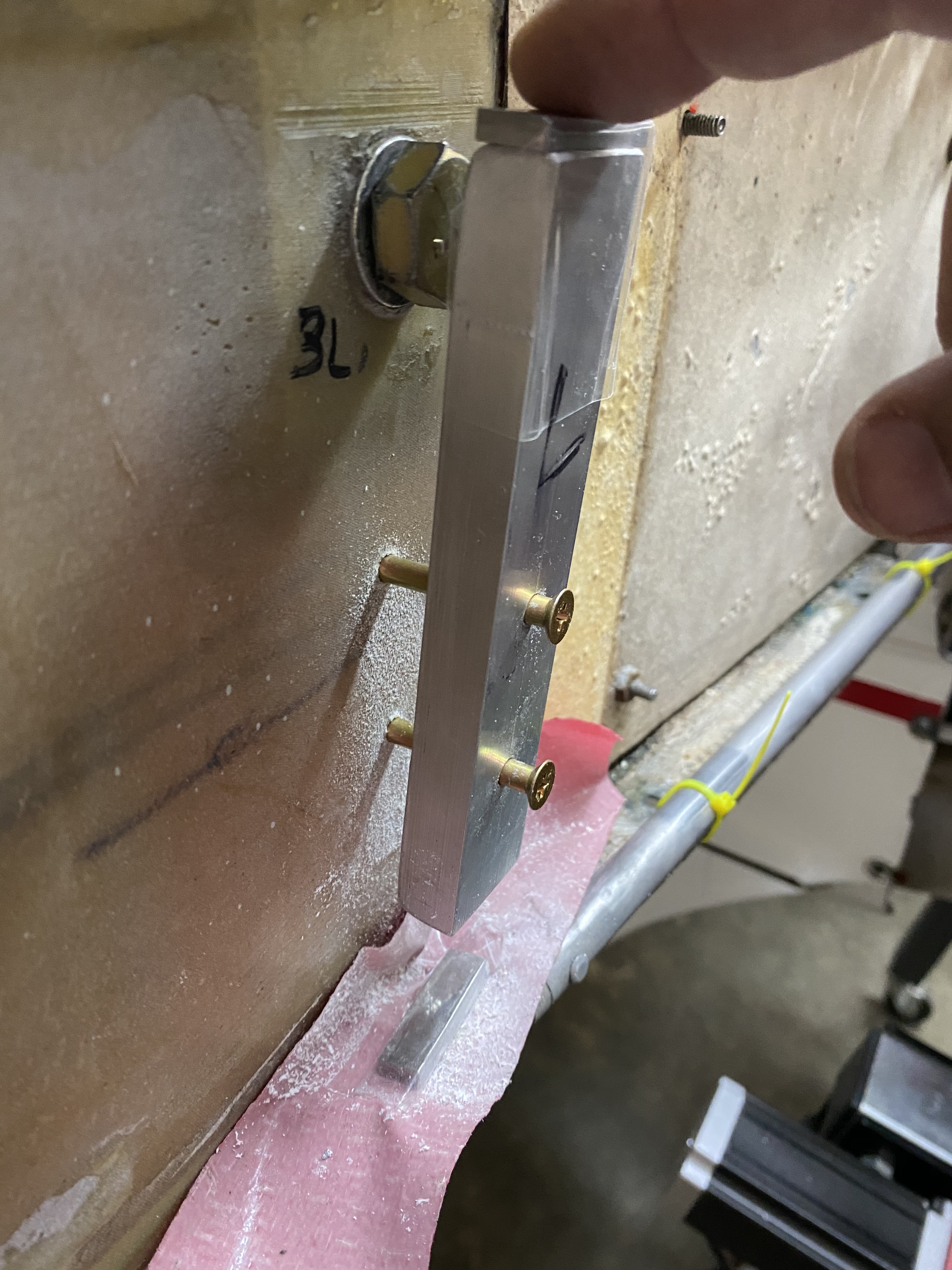
Thick aluminum U channel fitting tight over the bolt's head
|
These bolts are loaded in shear (perpendicular to the bolt's shaft) so the torque on them is not very high (200 in/lb or 22N/M)
Spoiler alert… this mod is awesome!
“Alright! This is going to require surgery, so let’s get started!”
Clearly the wings need to be removed first, so Chris and I got to work on that. We have done this multiple times due JT’s various upgrades, so there’s nobody else I trust more than Chris to help me with this task on JT.
 |
Chris helping me remove the wings
|
 |
| Right wing separated from the plane |
After that, I took JT home because of a number of other upgrades I had in mind.
 |
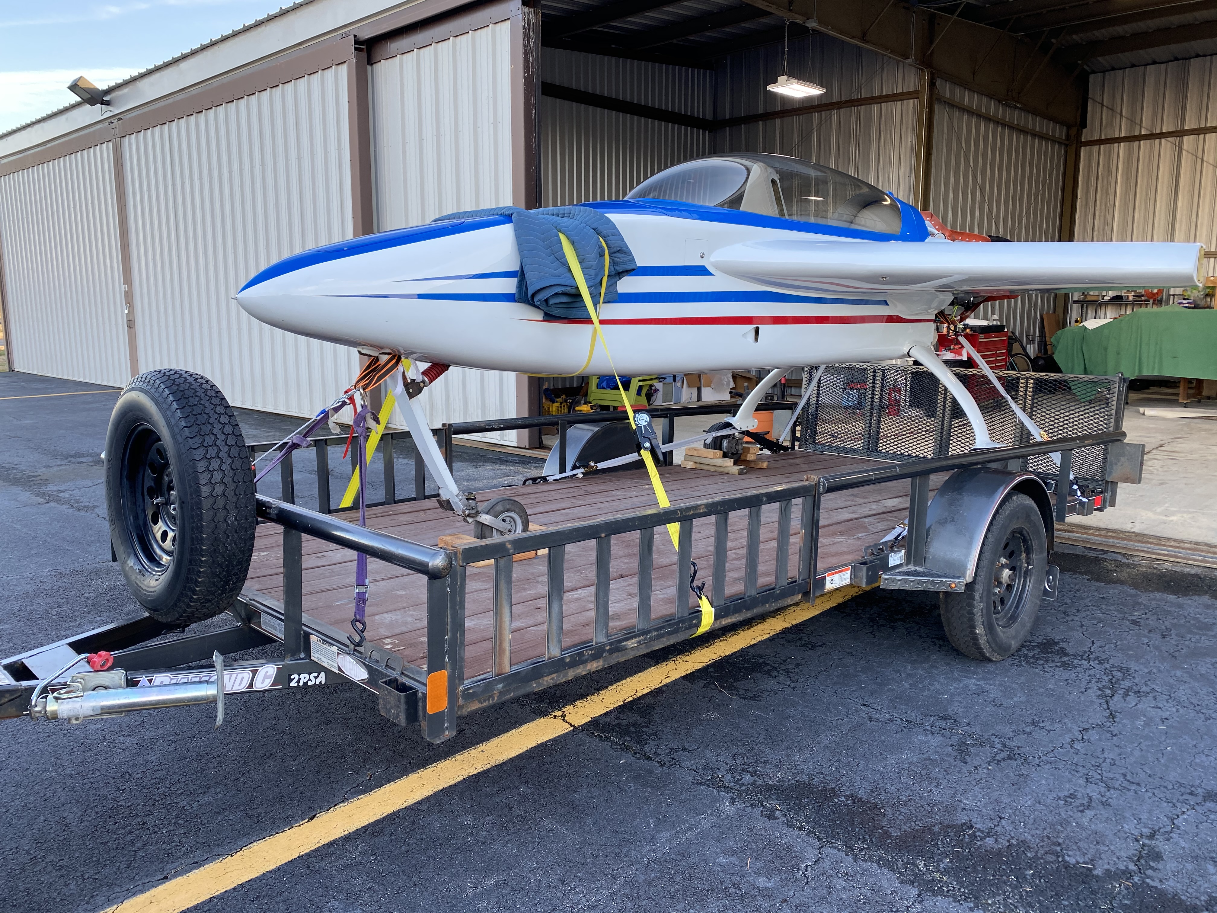
JT's going home for more comfortable working conditions
|
Once at home, I did get a lot more time to plan my approach, where to cut and how much, and how and whether to close the holes back up.
To reach the inner bolt holes to mount the U channels it was simply a matter of reaching into the spar from the back seat access hole, but the outer bolts are in an enclosed section, so the easiest access would be through holes on the far end caps. These caps are non structural, thin foam, with one ply on either side, and have holes for Nav lights wiring, and antenna coax cables. Some holes are bigger than others, and I know of a few builders that cut big holes there and never closed them up. Still, when I asked around, the consensus was that I should close them back up.
I picked a 4” (51mm) diameter hole saw, because I could fit my hand through it, and the rest went fast.
 |
Right side CS-spar end-cap hole planning
|
 |
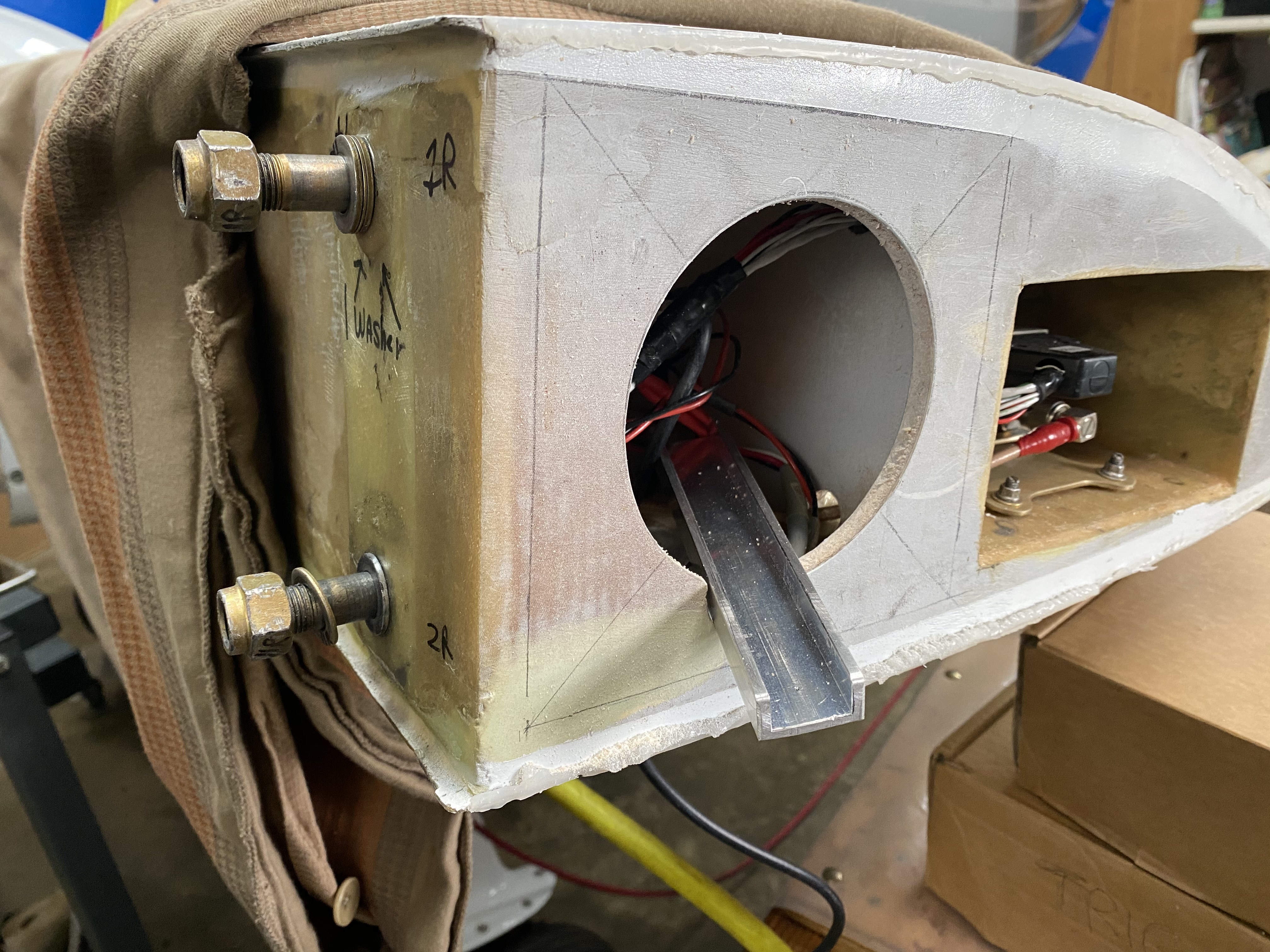
Right side CS-spar end-cap hole
|
 |
Wing bolts installed backward, and U channel going in for fitting.
|
 |
Using a scrap aluminum piece as a drill guide. This hole goes all the way through the U channel.
|
 |
A look with the U channel removed
|
 |
Added a nut plate to the U channel and reinstalled
|
 |
Screw with tapered washer to prevent fiberglass damage
|
 |
Left side CS-spar end-cap cut, bolts inserted, and U channel being fitted.
|
 |
U channel installed over the outer wing bolts
|
 |
Outer wing bolts in their permanent location
|
 |
Working on the right side CS-spar inner hole
|
 |
Bottom hole drilled, bolt installed. Top of U channel is fitted over the original wing bolt's head.
|
 |
Drilling the middle hole using the drill guide
|
 |
Bolt holes must be exactly on the U channel's centerline, or they won't line up when the U channel is installed facing back inside the CS-spar.
|
 |
Installing nut plates on the U channel
|
 |
I used dome-head rivets since I have a ton of them, and they don't require countersinking.
|
 |
U channel ready for action
|
 |
Wing bolt reinstalled backward, and screws holding on to the U channel.
|
 |
U channel in its final resting place
|
 |
| A view of the U channel inside the hollow CS-spar |
 |
| Going to work on the left side CS-spar inner-hole |
 |
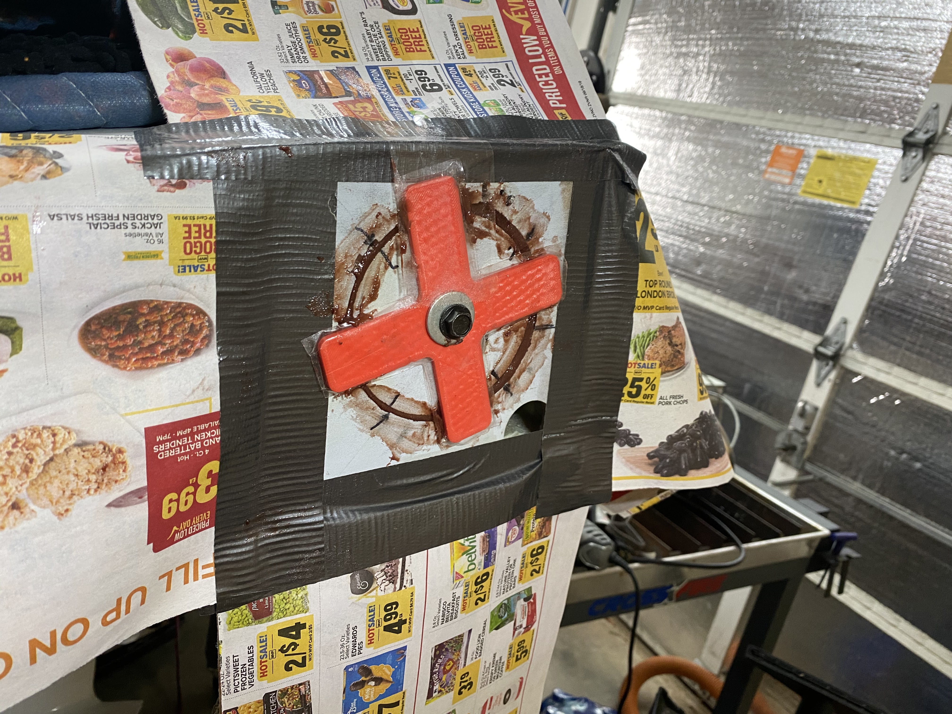
A gauge block on top of the U channel (with clear tape) allows the channel to hang from the wing bolt
|
 |
Holes drilled
|
 |
Here you can see how the U channel was hanging from the wing bolt
|
 |
Nut plates installed
|
 |
Left side of the mod completed. The three bolts are permanently installed.
|
 |
A closeup of the finished mod
|
 |
Left U channel holding on to the inner bolt (at the top)
|
 |
Another look at the U channel from the passenger seat access hole
|