Chronicling my Long EZ construction (and a few other things).
Disclaimer
This blog is for entertainment purposes only, and is not meant to teach you how to build anything. The author is not responsible for any accident, injury, or loss that occurs as a result of reading this blog. Read this blog at your own risk.
Before we start worrying about bending fuel lines, we need to make a decision on what to do about a couple of existing devices, and whether they should stay, or they should go. In particular the Andair gascolator, and the Allen fuel selector valve, both of which have served JT well for the past two decades.
Andair aluminum gascolator mounted on firewall
Allen tank selector valve
Let’s talk about the fuel valve first.
As much as I was lusting over a brand new Andair valve, my experience with the Allen fuel selector was that it worked well, and was paid for.
The Andair valve is probably the best looking one ever made
Not even close
I did notice some dried up blue stains on it, meaning it must have leaked at some point, mind you I had never seen nor smelled fuel in the cockpit, nevertheless the telltale signs were there.
What a fuel leak looks like
Leaking past the O-ring
Since a new Andair valve would be over $400 plus shipping, while new O-rings for the old valve less than a buck, I decided to rebuild it while I had it out, and save the money for other needs JT would surely develop soon enough.
The good news is that the process is very simple, and can be done rather quickly once you understand what the inside of the valve is like, otherwise there’s a slight chance you might cause some damage.
The valve consists of a machined housing, and a rotating piston with an integral 90º fuel channel cut into it. Both piston and housing are made out of aluminum.
Fuel channel machined into the piston
The piston has two large O-rings (MS29513-114 top and bottom) that prevent fuel from escaping the housing, and two smaller ones (MS29513-011) embedded into its cylindrical outer surface to seal off individual fuel passages as needed when the piston is rotated.
Replacing the O-rings is as easy as using a pointy tool and pulling them out of their grooves. Putting new ones in their place is just as easily done by hand, and unless discouraged by one’s Fuel Injection Manual, a little fuel lube might also help.
After removing the retaining steel clips at each end of the valve, the piston can be pushed out by hand from either side, although out the top of the valve body is a better choice, because it prevents the cross-springs from getting caught in the fuel channels of the valve body (more on that below). This is also when you might want to use a bucket to catch the four steel balls and two springs that will eject as the piston is withdrawn from the valve body.
Piston being pushed out the bottom (out the top is best)
To allow the piston’s 90º inner fuel passage to align with the housing’s fuel inlets/outlet during use, two springs push four balls into small detent holes on the valve’s top flange, thus providing tactile feedback of correct handle position when switching tanks. Each spring rests in its own through-hole drilled into the top of the piston at 90º with each other (on different planes), and pushes outward on a steel ball pair.
Through springs above the fuel section (all four steal balls removed)
This mechanism is smartly machined above the top O-ring, outside of the wet section of the valve body. These balls can actually be seen even with the valve installed in the plane, resting in the top flange’s detents, right below the valve’s handle.
Although nothing restricts the piston from coming out of the bottom, under certain circumstances doing so might expand the top springs into the fuel ports and get trapped by the descending piston. If you notice the piston jamming, just push the springs out the assembly before continuing. The trapped steel springs are hard to see if one hasn’t removed all AN fittings from the valve body, and damage might occur to the aluminum valve should one try forcing the piston down.
Fortunately this scenario can be mitigated by turning the piston 45º before pushing it out the bottom, or completely eliminated by pushing the piston out the top instead.
Moving on…
According to Wikipedia a gascolator “… acts primarily as a fuel drain for water and small particles of sediment and is usually found at the lowest point of an aircraft's fuel system”.
JT has one made by Andair on the firewall. A catch for water and sediments is never a bad thing, but one has to remember this device was primarily made to prevent water from collecting at the bottom of the carburetor bowl and stopping the engine. Since fuel injection doesn’t draw gasoline from a bowl, a few drops of water mixed with fuel will go right through without creating too much trouble.
Here’s what Don from Airflow Performance (a fuel injection manufacturer) has to say about gascolators in fuel injected engines…
“To fully understand the situation you must first understand why a gascolator was used in the first place. Back when carburetors were the only source of fuel metering on aircraft, water was a detriment to the operation of the engine. Of course water won’t burn but the main reason was that water being heaver than fuel would sink to the bottom of the float bowl. Water also has a higher surface tension than fuel. Since the main jets are located in the bottom of the float bowl and the metering head (the suction created by the Venturi to suck the fuel out of the bowl) is low on a carburetor, the water can actually block the flow of fuel through the main jets due to surface tension, thus starving the engine of fuel.
Enter the fuel injection system. There’s no float bowl, the fuel is under pressure (20-30 PSI). So in this case even if there’s some water in the system the fuel control will flow the liquid what ever it is. Granted the engine cannot burn water but there will be no interruption of the delivery of fuel to the engine…”
I will install a fuel filter before the auxiliary pump, and a finer one after it to catch smaller particles, but I decided not to reinstall the gascolator. I do sample fuel from the tanks before every flight, and will be able to pressure de-fuel the lines from tanks to firewall (I’ll explain in another post) should I find any water contamination in the tanks.
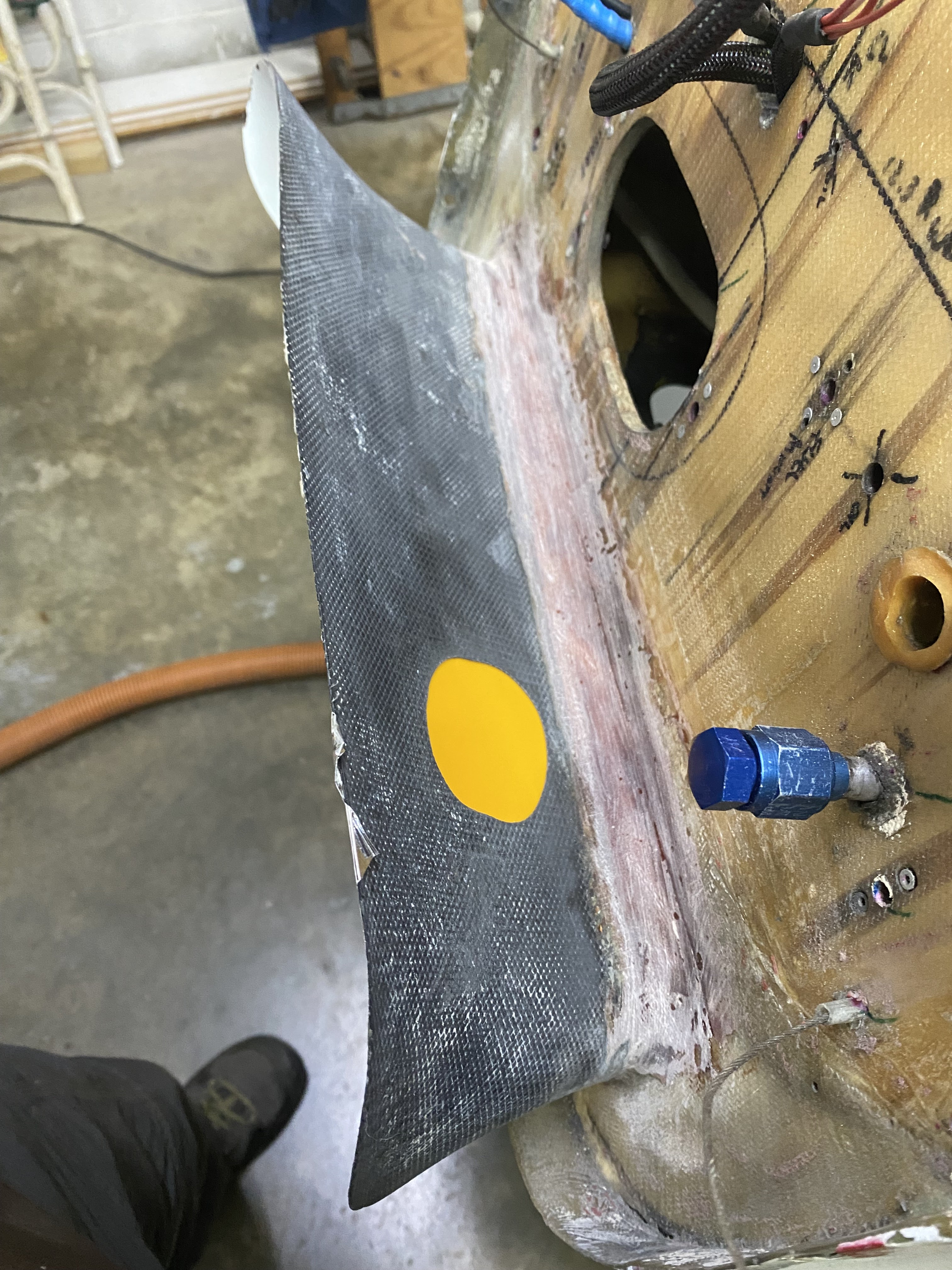
This left me with a pretty big hole in the diffuser that needed to be closed up.
Closing this hole without touching the paint will be... different
First, let's mask the paint we are trying to protect.
Next, we need a proxy for the missing surface. A squeegee is just perfect for this task.
Now we can begin to work
After a lot of masking, I cut a few fiberglass patches to close the hole.
Glassing alone from the top would be ok, but not blend in smoothly.
A little bit of flox will create a tough, smooth, continuous surface on the bottom.
Pre-pregged fiberglass patches going in
Patches left extra wet for upcoming peel-ply
Repair completed with peel-ply application
Next day, with peel ply removed.
After a bit of sanding
Top looks pretty good, let's go check out the bottom surface of this repair.