Disclaimer

This blog is for entertainment purposes only, and is not meant to teach you how to build anything. The author is not responsible for any accident, injury, or loss that occurs as a result of reading this blog. Read this blog at your own risk.

Tuesday, July 31, 2012

Ch. 6 - Fuselage assembly - Part 1


Assembly test
With 99% of the work done on the bulkheads, I just couldn’t resist putting them together to see how they’d look.
It took quite a lot of force to bend those longerons, but the fuselage looks awesome. 

Going from 2D flat pieces, to a 3D fuselage is amazing. 

Now, when the neighbors ask to see “the plane”, I can really show them something, rather than ask them to imagine it.

All bulkheads clamped together (F22 is backward in this photo - thanks Ary)


The rear seat space is HUGE :-)

Firewall is just sitting there


(F22 is still backward in this photo... don't want to confuse anyone!)

(Guess what? F22 is once again backward in this photo - no worries, I  mated it correctly later on)

The light at the end of the tunnel


Ch. 5 - Fuselage side RH - Part 8


Trimming more fiberglass   (1.4 hrs)
This morning the fiberglass was hard as a rock.

Cured fiberglass with peel-ply over it

I trimmed the excess off, and sanded it to shape, then got on with the same task I performed last night on the right sidewall, grinding the glass down to WL 12.35.

Action shot of glass removal

Most glass removed

It turned out quite well again.

"Water Line" 12.35 is clear!

Checking for flatness with metal ruler


Ch. 5 - Fuselage side LH - Part 6


Trimming hard fiberglass   (1.4 hrs)
While the slurry was curing on the right sidewall, I took some time to take care of a remaining issue on the left sidewall.
The plans specify not to glass above "Water Line" WL 12.35 (12.35" up from the zero reference level). That’s more easily said than done! It is pretty hard to be that precise while applying the 15 plies of BID. So, I decided not to worry about such precision during glassing, and go back and trim it at a later date.
I knew it could be done precisely, but I was not quite sure how to do it.
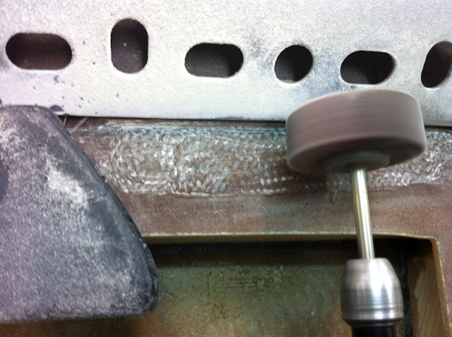
What I used is a sanding attachment mounted to my Dremel tool, and a metal bar to prevent me from going to far with it, and to keep things straight. 

I know, I know, this is the best I could come up with in a short time. But it worked!

I also stuck the business end of my shop-vac near the cutting area, to avoid making a cloud of itchy fiberglass. 

The vacuum hose worked really well to keep things clean

I used a straight edge to make sure I didn’t cut into the lower 6 BID layers, and the result was excellent.

Buildup shaved to WL 12.35

I will do more of this kind of grinding to the sides of the buildups, after I finalize the position of the gear mounts.


Ch. 5 - Fuselage side RH - Part 7


Glassed the right gear hard point   (6.0 hrs)
This part always takes more time than you’d think, especially when you consider the dimension of what you end up with.
I cut a bunch of foam pieces, and like a puzzle I fitted them into the space between the wooden pieces. Then I mixed up some West System epoxy and micro-balloons, and used it to glue the pieces in place.

7 pieces of leftover foam glued together, make up the filler material.

I had to wait a few hours for everything to cure, then I sanded everything even, masked the area with tape, and slurried it.

Packing tape protects the wood pieces from the micro-slurry application

With the masking ripped, I painted pure epoxy onto the wood pieces.

Epoxy to go on wood pieces

Then I laid 6 plies of BID at 45˚ over the entire area.

6 plies of BID

Finally, I added the two local 15 BID plies buildups, and peel-plied everything.

I hope it still looks this good in the morning


Sunday, July 29, 2012

Ch. 5 - Fuselage side RH - Part 6


Rear longeron  (1.6 hrs)
This is going to look like a carbon copy of what I did on the left side, which is a good thing.
I am basically floxing another triangular longeron stock piece, to the rear side of the lower longeron, so that its cross section becomes square.

Lower stringer cut and ready

Stringer with flox

A couple of clamps ought to do it!


Ch. 4 - Firewall - Part 3


Front side  (4.7 hrs)
I decided to modify slightly the way the screws are secured onto the firewall. 
The plans call for drilling the holes, countersinking them, then use epoxy on the screws to try to tie them to the fiberglass to go over them. The problem is that you could possibly tighten the bolts enough to break this weak bond. Should this occur, the screws would rotate loosely in the countersunk holes, and there’d be no correcting it, since the head of the screws are butted against the back of the spar, never to be seen again.
My buddy Wade suggested I grind the sides of the screws, and dig matching slots in the firewall, rather than countersinking. This is quite a lot more detail work, but well worth it, since it provides a mechanical impediment to the screws rotation. I added flox to the slots, and to the heads of the screws. I don’t think these babies will be turning on me anytime soon.

Screws before and after

Milling tool and slot outline

Screw slot ready

Dry fitting

Firewall back side

Wider shot of both screw sets

Adding flox


I then took some time to drill, and fit the mounts for the rudders pulleys. These are made out of steel, and they come from the “Cozy Girls” in two parts that need to be matched correctly, so that the pulley axle holes line up.

Rudder pulley bracket getting fitted

With those out of the way, I cut a ply of BID, and glassed the front of the firewall.

Using plastic to help squeegee the single ply of BID

Peel-ply sheet over fiberglass


Here’s a detail of the screws under the curing fiberglass:

Screws buried into the wood, floxed, and glassed.

Saturday, July 28, 2012

Ch. 4 - Firewall - Part 2

Glassing the rear side of the firewall  (1.0 hrs)

With the lower longeron curing, I decided to start taking care of some old business.
The firewall still needs some work. One ply of BID needs to go on its back side, screws need to be floxed in from the front, then the front needs to be glassed as well.
I’ll take care of the back side first. As you’ll see, it’s pretty standard stuff at this point.

Roughing up the surface with sand paper

Cutting BID at 45˚

Using plastic to smooth BID and eliminate bubbles


After trimming the overhanging BID

Peel-ply sheet over BID

Those pesky epoxy bubbles appeared once again under the peel-ply, right after I left the shop. I decided not to mess with them anymore, and leave them alone. I'll just sand them after removing the peel-ply.


Annoying epoxy bubbles appearing under the peel-ply


One thing that I have kept forgetting to take pictures of until tonight, is the type of knife blades I've been using to perform the "knife trimming" operation.


"Knife trimming" the still gummy fiberglass


I bought these at LOWES. They are designed to trim roofing material, but boy, do they work like magic on fiberglass! 


When the glass is still at the semi-hard stage, these blades go through it like butter, and the hook thing prevents the blade from slipping, and cutting where you didn't intend to. 


Just get them, you won't regret it.


So, here's a last photo for tonight, after knife trimming.


Peel-ply covering the curing fiberglass


Ch. 5 - Fuselage sides RH - Part 5


Lower longeron  (1.2 hrs)
The lower triangular longeron went on pretty quickly. I cut a few slits into it to aid in bending around the fuselage bottom, and used some nails to hold it in place.

Positioning the lower longeron using nails

Lower longeron in place

I then mixed some flox, buttered the back of the longeron, and repositioned it with the nails.

Longeron floxed to the right sidewall

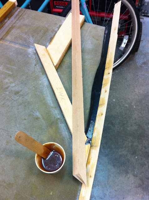
Using the same notched scrap wood I used on the left sidewall, I put as much weight to bear as I could find, and cleaned up the excess flox.

Longeron curing under pressure

Ch. 5 - Fuselage sides RH - Part 4


Proper positioning of LWX and LWY  (2.0 hrs)
Aligning the wood pieces LWX and LWY on the left sidewall was challenging to say the least, and even with the sidewall cut to the exact plan dimensions, the scale drawings were a bit off (more than I would have liked). I did get them as close to the drawings as possible, but total fidelity was not in the cards. I'm blaming the 1980s reproduction technology.
While a bit disappointed in the quality of the drawings, a lot of the inaccuracies will be magically corrected during final assembly with careful alignment.
Perhaps one of the more important points is that, however inaccurate the geometry of LWX/LWY positioning on the left sidewall turned out, the same should be replicated on the right sidewall, to ensure even fitting of the wing spar.
Because the drawings could not be counted on for absolute precision, and since positioning by hand tends to introduce its own errors, I needed to devise some sort of apparatus to enable me to precisely mirror this wooden geometry on the opposite sidewall.
While considering such a thing, I decided that the most important LWX/LWY dimensions should be the ones measured from the top of the longeron, and from the aft edge of the sidewall, both acknowledged reference points. The jig I was considering would thus have to be able to capture these dimensions, and reverse them, like a mirror, without losing any accuracy.
These requirements were enough to cause quite a bit of head scratching, but I eventually settled on what turned out to be a simple solution, that required no actual measuring, while providing total accuracy, even when transposed.
I decided to place strips of wood on top of, and in tight contact with the longeron (#1), LWX (#2), and LWY (#3), then capture their relative positions by laying a flat a board over them, and driving screws into them from the top.

Laying out the jig

Pattern captured with board

Rear view

Front view


I basically created a wooden pattern for replicating the LWX/LWY geometry. To make it usable on the right sidewall, it had to be reversed though. So, I flipped what I had at this point upside down, and placed another flat board over it. I then drove a new set of screws into the wooden strips from this side, flipped it over again, and removed the original screws, and the original board.

Left sidewall jig flipped over to make the right sidewall jig

New board applied to the top

Jig flipped over and original board removed, yielding the opposite side jig.

Just like that, I had the perfect mirror image I was looking for.
All I had to do now was to secure the jig to the right sidewall, and fill in the new LWX and LWY.

Right side jig in position

New jig in action, positioning LWX and LWY.

After an initial dry fit, followed by many measurements to confirm my expectations, I floxed LWX and LWY in position, confident that I had achieved the closest possible left to right match.

LWX and LWY floxed to the right sidewall

Final measurements after the flox dried revealed no measurable differences between the two sidewalls.

Jig removed, LXY and LWY curing.

Finished product


UPDATE: Here's what I discovered reading through the 1800 pages of Canard Pusher newsletters late last night:


CP #27 page 6 (Builder Hints) Aft fuselage side shape, plans page 5-2
A number of builders have noted that the A-5 drawing has a different shape the that obtained when fabricating the fuselage sides per the page 5-1 dimensions. This approximately 0.2" error will not present a problem if you follow these instructions: Carefully follow all the dimensions on page 5-1. This will assure that the firewall will fit. Do use the 5.8 and 6.9 dimensions on A-5 and be sure the extrusions are perpendicular to the top longeron. Ignore the small difference between the bottom shape and that on A-5.