Bushings upgrade (16.0 hrs)
The only reference to steel bushings being added to the aluminum landing gear brackets comes not from the plans, but from an inference uttered as a side note in CP #46 “builder hints”:
... If you bought your extrusions from Brock, you will note that they have flanged, steel bushings pressed into the aluminum angles, these steel bushings are available separately from Brock and are an excellent idea...
That’s it! No drawings, no measurements, no guidance, nothing!
Welcome to “plan’s built”, where the only thing that separates the plans from a flying plane is... everything!
I am not complaining, well... maybe a little, but obviously I knew this before diving into it. It’s just that occasionally you wish you didn’t have to reinvent the wheel every single time.
Ok, bitching session’s over. I do feel better, thank you. Back to the issue at hand.
The steel bushing debate stems from the idea that a steel/steel load path is preferable to steel/aluminum anywhere there might be some relative movement between parts.
This makes sense to me, since the landing stresses transfer from the wheel, to the gear leg, to the big steel gear bolt, then to the aluminum gear bracket. Unfortunately, the tiny gap between the bolt and the bracket, works against it with every landing, since the steel bolt will try to enlarge the hole during a lifetime of airplane use.
In case you were wondering why I don’t just call Brock and order some bushings, it’s because sadly they went out of business a long time ago.
Polling my builder friends for ideas, I found a lot of different opinions, so I decided to incorporate some of their best ideas, with some of my actual dimensions, and perform some testing on scrap pieces.
 |
| Initial dimension brainstorming session. |
 |
| Initial testing on scrap aluminum |
Probably the most important question to address is about the thickness of the bushing’s sidewall. Something to consider here is that the thicker the bushing becomes, the less clamping surface remains between the gear tabs (aka bracket), and the steel tube that is held between the tabs.
 |
| Should the bushings get thicker, the area of available contact would become smaller. |
To bring this idea to an extreme, if the outer size of the bushing became equal (or greater) to the size of the tube, the tabs would not be able to contain it, and it could push right out, tube, bolt, bushings and all. So the biggest dimension the bushing can have, must be somewhat less than the outer diameter of the gear tube (< 0.625”, < 15.875 mm).
It would seem then that the thinner the better, but what is the thinnest bushing that I can press without deformation?
I experimented successfully with a wall thickness of 0.045” (1.143 mm), but had some warpage when I stepped it down to 0.030” (0.762 mm).
 |
| Hard to see in this picture, but the left thinner bushing is no longer completely round. |
A second issue to consider is whether the bushing should have a flange, or not. Flanged seemed the way to go for a number of practical reasons, not least of which are greater ease of installation, better control over its alignment, and more precision in determining the depth of the insertion.
Great, we are making progress!
But how thick should this flange be?
Considering that warping started to occur at a thickness of .030”, I wanted to stay above that value, but I couldn’t go too thick, because of the necessity to leave at least 2 threads sticking out of the nut when tightened.
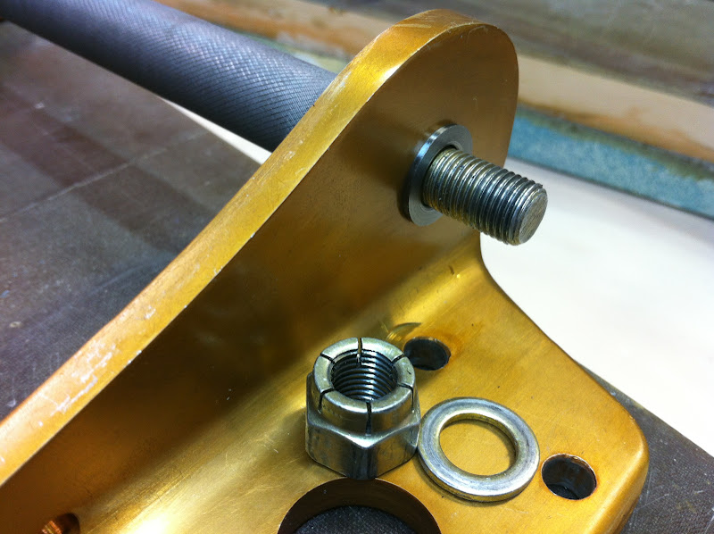
I measured a 0.100” (2.54 mm) gap between the nut, and the second thread of the bolt. This would allow for two flanges up to 0.050” thick. I went with 0.045” to give myself a little room.
 |
| This is a picture of the end result, showing the 2 required threads |
At first glance, it would seem that the part of the bushing buried into the tab, should be just as long as the tab’s width .250” (6.35 mm), but any part accidentally sticking out beyond the tab could compromise the proper seating of the tube onto the tab itself.
My friend Walter warned me to keep the bushing slightly shorter than the tab so I decided on 0.245”, or 0.005” short.
Fortunately, the inner diameter of the bushing was always a known quantity measuring 0.375” (9.525 mm), and determined by the size of the bolt.
Below are the final dimensions I used. They worked for me, and I am not advising anyone else to use them, I just wanted to highlight the lengthy process it took to arrive to even this smallest of parts.
 |
| Cross section of bushing (left) and tab (right) - drawing not to scale |
You might notice that the bushing’s OD is bigger than the tab ID. The difference is 0.0015” (0.0381 mm), and it is designed to give me a nice and tight interference fit.
If you wonder where the 0.4688” ID came from, it came from the 15/32” reamer (11.9062 mm) I used. Using a reamer guaranteed the hole to be round, and exactly the nominal size. I could then give all my attention to cutting the 0.4703” bushing OD, as accurately as possible with my lathe.
 |
| First bushing made to specs. Note the 4 threads sticking out of the bolt in the background. |
 |
| Quadruplets |
 |
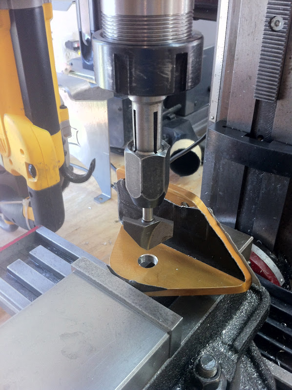
| Enlarging the original bolt hole |
 |
| Reaming the hole to accept the new bushing |
 |
| Chamfering the opposite edge to allow the bushing to seat all the way |
 |
| First torpedo in the tube |
 |
| Using the precision milling vise to convince them that they were made for each other |
 |
| These looks awesome! If I can say so myself. |
 |
| Bushings resting 0.005" below the tabs' surface |
 |
| Bushing in action |
Awesome job Marco! Bravo!
ReplyDeleteThanks Mike, I can finally consider these brackets done at last.
ReplyDelete