Disclaimer

This blog is for entertainment purposes only, and is not meant to teach you how to build anything. The author is not responsible for any accident, injury, or loss that occurs as a result of reading this blog. Read this blog at your own risk.

Monday, August 27, 2012

"Tooling up" - Mill's Z axis


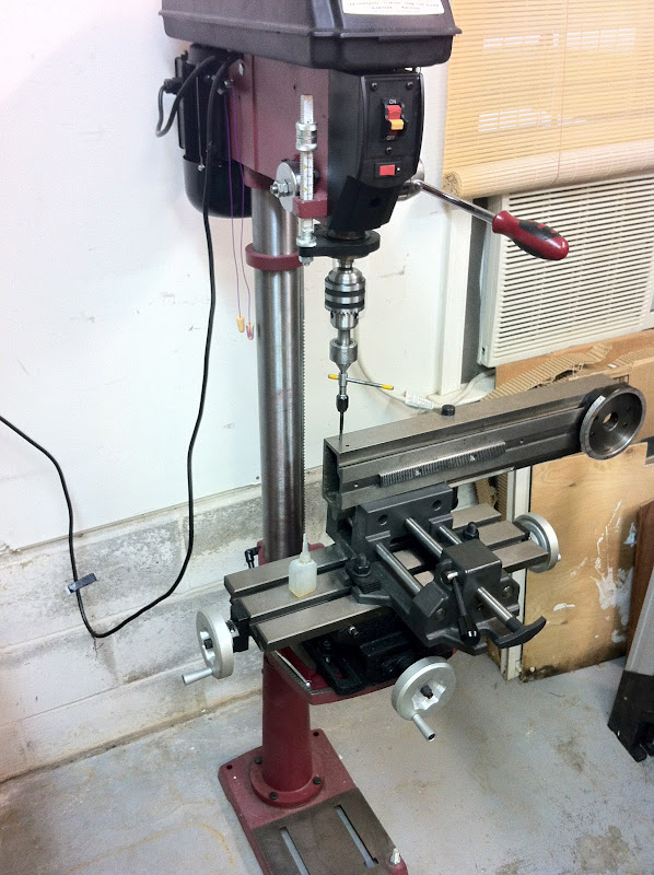
Mini-Mill digital Z axis conversion

Yesterday, I started work on a little side project that should have only taken a few hours, but instead ended up taking all day.  Don’t they all!

One of the things I wasn’t too happy about with my mini-mill, is the fact that the Z axis (vertical) has quite a bit of backlash due to the play in the gears, and this has a small but bothersome effect every time I use it. 

Let’s say for example that I have just lowered the mill head until the cutting tool barely touches the part, so that I can find and set the zero height position. Next, I would raise the tool to reposition it somewhere else on the part I am working on.  Backlash is such that it takes some turning of the knob in the opposite direction before the tool even starts moving up again. The same thing happens when I later want to lower the tool again to cut in the new position.

Backlash demo on converted mill

The only way to quantify how far up or down I have moved the tool, is by reading the graduations on the knob itself. Problem is that by now the numbering is all screwed up, and will give readings of a movement that hasn’t really happened, at least to the extent indicated on the dial.

To compensate for this, I have to first take up all the backlash every time I change the direction in which I turn the knob.  Then, make a note of when the head starts to finally move.  Finally, re-zero the indexing on the knob before its numbers can be trusted again. This is not always possible, or convenient all the time.

Backlash is a real pain in the rear.  It slows me down, complicates every thing I do, and leads to inaccuracy.  This troubling phenomenon occurs in different amounts on all three axes, but has been more of a problem in the vertical direction.

Fortunately for me, included in my lathe and mill purchase came a few extras, among which was a caliper-style digital measuring device.  I decided to use it, and modify the mill in such a way that any actual head movements correspond to a new caliper position.

The beauty of this method is that no matter how bad the backlash is, the caliper only moves when the head moves.  The end result is that I end up measuring only actual tool movements, and the backlash issue is eliminated altogether.

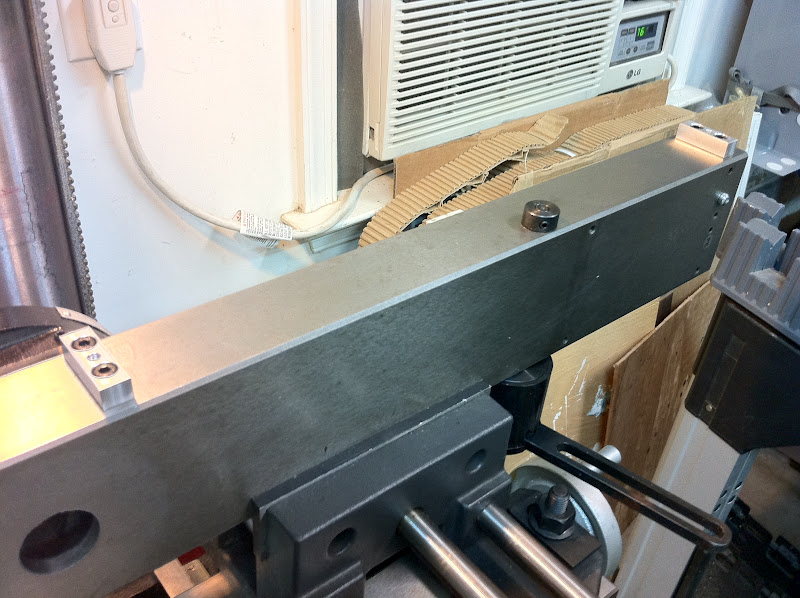
Unfortunately, I couldn’t just screw the caliper to the mill column, because it needed to clear a cylindrical part of the lift spring mechanism that protruded through the right side. So, I decided to make some aluminum standoffs on which to mount the caliper.

Here are a few pictures of the conversion in progress.


Aluminum from which the standoffs were cut, plus standoffs before and after

Caliper-style device on the standoff

Finished standoffs

Tapping the top side of the mill column

Top standoff bolted in place

Tapping the lower holes in the mill column

The cylindrical object in the middle of the column is the reason for the standoffs

The whole shebang in position

Tapping the hole on the head of the mill

Digital measuring device on the mill, ready for use


Saturday, August 25, 2012

Ch. 5 - Fuselage sides - Part 6


Foam removal method  (0.5 hrs)


This Long EZ project is undoubtedly a ginormous exercise in problem solving. 

Every unlisted task you are faced with has multiple solutions, some of which are better or more efficient than others, most of which  will be still unknown to you, until you “discover” them, as in "make them up as you go".

This one is another of those unspoken things that have to be done, but that appears nowhere in the literature, and there are thousands of these everywhere. 

Today’s task is to prepare the holes I drilled on the sidewalls to receive a washer and a nut.

Well, the holes I drilled were 0.25”, but the washers are 0.50”, so some foam will have to be removed from the outside of the sidewalls, so that I can put washers and nuts on the bolts, and tighten them.

Like most every other task I have dealt with, this one had me scratching my head for a few days, aggravating the bolding spot on the very top.

What I was hoping to achieve was a repeatable process, with minimal foam removal to keep from having to add heavier micro, and hopefully quick and easy as well.

As you will see, I am happy to report that this task was disposed of in a very short time, with excellent results, thanks to a new (to me) approach to cylindrical foam removal.

If you have ever bought a Dremel tool, it probably came with attachments that you don’t even know what they are for. Mine was the same way, I bought it maybe 20 years ago, and I still had a few heads that have never been used.

I decided to give four of these a try and, though I'm sure they were never intended to be used this way, they worked like magic on the foam.


Seldom to never used Dremel tools, plus a 1/2" end mill.


I also used a 0.50” end mill to cut up some of the foam toward the bottom that the attachments couldn’t get to.


Using this technique, I was able to complete both sides very quickly.


Right outer fuselage sidewall


The holes are perfectly cylindrical, and are the smallest needed to take care of business.


Fiberglass from the other side showing at the bottom of the hole


There is still a little clean up to be done at the bottom, but I came up with a different technique to do that.

You might remember that I cut the gear brackets bushings from a 0.625” steel rod, which turns out to be close enough to size of the foam holes. Since I still had a lot of it laying around, I glued some sand paper to one end of it, and used it between my hands, like I was trying to start a fire, and sanded the fiberglass at the bottom of the hole until it was smooth.

Glueing sandpaper to steel rod


Sand paper trimmed with razor knife


Sanding the bottom of the holes


Clean enough to accept a washer and a bolt


Now that the outer sides are ready, it’s time to flox and bolt these gear brackets onto the sidewalls, once and for all.


Tuesday, August 21, 2012

Ch. 5 - Landing Gear mounts - Part 8


Bushings upgrade  (16.0 hrs)


The only reference to steel bushings being added to the aluminum landing gear brackets comes not from the plans, but from an inference uttered as a side note in CP #46 “builder hints”:

... If you bought your extrusions from Brock, you will note that they have flanged, steel bushings pressed into the aluminum angles, these steel bushings are available separately from Brock and are an excellent idea...

That’s it! No drawings, no measurements, no guidance, nothing!

Welcome to “plan’s built”, where the only thing that separates the plans from a flying plane is... everything!

I am not complaining, well... maybe a little, but obviously I knew this before diving into it. It’s just that occasionally you wish you didn’t have to reinvent the wheel every single time.

Ok, bitching session’s over. I do feel better, thank you. Back to the issue at hand.

The steel bushing debate stems from the idea that a steel/steel load path is preferable to steel/aluminum anywhere there might be some relative movement between parts. 

This makes sense to me, since the landing stresses transfer from the wheel, to the gear leg, to the big steel gear bolt, then to the aluminum gear bracket. Unfortunately, the tiny gap between the bolt and the bracket, works against it with every landing, since the steel bolt will try to enlarge the hole during a lifetime of airplane use.

In case you were wondering why I don’t just call Brock and order some bushings, it’s because sadly they went out of business a long time ago.

Polling my builder friends for ideas, I found a lot of different opinions, so I decided to incorporate some of their best ideas, with some of my actual dimensions, and perform some testing on scrap pieces.


Initial dimension brainstorming session.

Initial testing on scrap aluminum

Probably the most important question to address is about the thickness of the bushing’s sidewall. Something to consider here is that the thicker the bushing becomes, the less clamping surface remains between the gear tabs (aka bracket), and the steel tube that is held between the tabs. 


Should the bushings get thicker, the area of available contact would become smaller.

To bring this idea to an extreme, if the outer size of the bushing became equal (or greater) to the size of the tube, the tabs would not be able to contain it, and it could push right out, tube, bolt, bushings and all. So the biggest dimension the bushing can have, must be somewhat less than the outer diameter of the gear tube (< 0.625”, < 15.875 mm).

It would seem then that the thinner the better, but what is the thinnest bushing that I can press without deformation?

I experimented successfully with a wall thickness of 0.045” (1.143 mm), but had some warpage when I stepped it down to 0.030” (0.762 mm).


Hard to see in this picture, but the left thinner bushing is no longer completely round.

A second issue to consider is whether the bushing should have a flange, or not. Flanged seemed the way to go for a number of practical reasons, not least of which are greater ease of installation, better control over its alignment, and more precision in determining the depth of the insertion. 

Great, we are making progress! 

But how thick should this flange be? 

Considering that warping started to occur at a thickness of .030”, I wanted to stay above that value, but I couldn’t go too thick, because of the necessity to leave at least 2 threads sticking out of the nut when tightened. 

I measured a 0.100” (2.54 mm) gap between the nut, and the second thread of the bolt. This would allow for two flanges up to 0.050” thick. I went with 0.045” to give myself a little room.


This is a picture of the end result, showing the 2 required threads


At first glance, it would seem that the part of the bushing buried into the tab, should be just as long as the tab’s width .250” (6.35 mm), but any part accidentally sticking out beyond the tab could compromise the proper seating of the tube onto the tab itself. 

My friend Walter warned me to keep the bushing slightly shorter than the tab so I decided on 0.245”, or 0.005” short.

Fortunately, the inner diameter of the bushing was always a known quantity measuring 0.375” (9.525 mm), and determined by the size of the bolt.

Below are the final dimensions I used. They worked for me, and I am not advising anyone else to use them, I just wanted to highlight the lengthy process it took to arrive to even this smallest of parts.


Cross section of bushing (left) and tab (right) - drawing not to scale


You might notice that the bushing’s OD is bigger than the tab ID. The difference is 0.0015” (0.0381 mm), and it is designed to give me a nice and tight interference fit. 

If you wonder where the 0.4688” ID came from, it came from the 15/32” reamer (11.9062 mm) I used. Using a reamer guaranteed the hole to be round, and exactly the nominal size. I could then give all my attention to cutting the 0.4703” bushing OD, as accurately as possible with my lathe.


First bushing made to specs. Note the 4 threads sticking out of the bolt in the background.

Quadruplets 

Enlarging the original bolt hole

Reaming the hole to accept the new bushing

Chamfering the opposite edge to allow the bushing to seat all the way

First torpedo in the tube

Using the precision milling vise to convince them that they were made for each other

These looks awesome! If I can say so myself.

Bushings resting 0.005" below the tabs' surface

Bushing in action


Wednesday, August 15, 2012

Ch. 5 - Fuselage sides - Part 5


Drilling the gear bracket holes  (7.9 hrs)


To tell you the truth, I worried I'd screw this up and have to throw away the whole sidewall. 

To better my chances, and help me drill all of the 16 holes perpendicular to the sidewall, I ended up making a drilling block. 


Drilling block in action


There's no going back now!

The bolts in the pictures are not the final ones, they are just some extra long bolts I had laying around.  


Test fitting


Everything will have to come down one more time because I still have to fabricate, test, and fit 4 additional LGMA steel bushings, before I can consider this chapter finished. 


Monday, August 13, 2012

Ch. 5 - Fuselage sides - Part 4


Extending LWY  (1.0 hrs)


I must have cut my LWYs slightly short, because they don't extend completely through the firewall. I’m not sure why the plans don’t leave them a couple of inches longer, to be trimmed later.


This is not a big deal. I could fill the gap in with a heavy blob of flox, but I wanted to try something different, and lighter.

I decided to lengthen them slightly. Unfortunately, the LWYs cross section offers a small surface area to bond an extension to, and because more bonding surface equals more strength, I wanted to try to increase the surface area that the flox would adhere to as much as possible. 

This is what I came up with. 


Extensions with 30˚ grooves cut with the table saw


Matching groves in LWY cut by hand with a saw


Left sidewall with LWY extension floxed

Right sidewall with LWY extension floxed

Extensions curing overnight

Finished extensions now protruding through the firewall


Thursday, August 09, 2012

Ch. 4 - Firewall - Part 4


Cutting the longeron holes  (4.0 hrs)


I have been waiting to cut the holes in the firewall until the sidewalls were ready, and now that they are, it is time to take care of this item.

Having previously drawn all the component details on the forward face of the firewall, has proven to be a really good idea, and has helped in many ways. I have been able to easily locate the screw holes for example, and now I can use the accurate drawings to determine where the longeron holes should be cut.

I will be using the same Dremel milling tool that I used before to cut the holes in the instrument panel. The only difference is that I will be cutting through wood, rather than foam.

To help make straight cuts, I enlisted the help of my favorite steel angle scrap, and to keep things clean and help me see how the cut is going, I set up the shop-vac.


Everything in place to start cutting


The system worked fairly well. Nothing that couldn’t be cleaned up with a little sandpaper anyway.


Pretty straight cuts


3 longeron holes completed

I used scrap wood I saved earlier on to check for size.


Checking for size


Same thing, different hole.


I tested and fitted the firewall on both sidewalls individually at first.


Test fitting on right sidewall


Test fitting on left sidewall


Then, I tried it on on both sides together, to make sure there were no surprises.


Firewall holding up both sides