Disclaimer

This blog is for entertainment purposes only, and is not meant to teach you how to build anything. The author is not responsible for any accident, injury, or loss that occurs as a result of reading this blog. Read this blog at your own risk.

Sunday, October 28, 2012

Ch. 6 - Fuselage assembly - Part 11


Strakes openings placement (1.0 hr)  


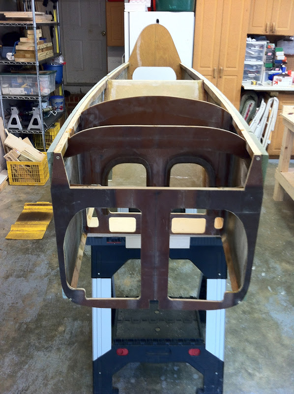
For the first time since I started putting bulkheads and sidewalls together, the fuselage has left the table and is now on sawhorses, holding itself together at last.


Still upside down on sawhorses


The next step at this point would be to put the bottom foam on the fuselage (top in the previous picture), and trace the outline of the floor onto the foam, from the inside. The only problem is that when I made my initial purchase, I never did order the foam for the bottom. 

Doh!

A quick call to Wicks, and the foam was in the mail, but now I'd have to wait another week to get the stuff.

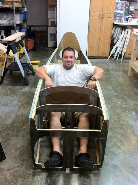
Perfect time for some more glamour shots, after turning the fuselage right side up!


Right side up for the first time


Flintstones' car (note my legs sticking out of the bottom)


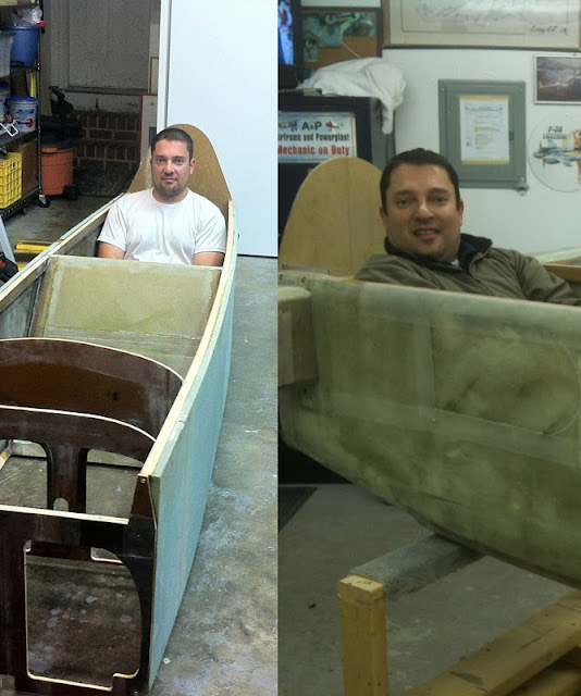
Look at the difference 2" make. The longerons are buried into my shoulders in the per-plans rear seat on the right.

With nothing on the agenda, I decided to trace the holes for the strake access on the fuselage sides. That will help me position the peel-ply when I later glass the exterior of the fuselage.


Rear seat, strake access hole

Front and rear seat hole patterns


One of the plan changes I decided to incorporate in my plane, is what I have called the "Steve's elbow mod" in the past. Essentially it creates more elbow room for the rear passenger, by extending the trailing edge of the rear strake access hole further back. 

In my case the strake cutout begins 13" (33 cm) from the front side of the firewall, compared to the original 21.5" (54.6 cm). 


Thursday, October 18, 2012

Ch. 6 - Fuselage assembly - Part 10


Landing gear bolt access hole (1.2 hrs)  

In the future it might come a time when the landing gear needs to be removed, so access to the gear bolts needs to be provided for, by way of holes cut into the back seat.

The manual addresses this with a note at the bottom of page 6-3.

"Really?! Now you tell me!"


I suppose this is going to look like an afterthought, nevertheless it is now necessary to cut another hole into my beautiful rear seat.

Luckily the right bolt has a clear path through the seat already, so I can leave that side alone.


No problem reaching this bolt


The left side is where the problem lies. There is just no way to remove the bolt.


This bolt cannot be removed as is.

I've got to cut another access hole into my "Swiss cheese" rear seat


Using a drill first, and then my dremel tool, I was able to open up the smallest hole big enough for the bolt to fit through.


"Coming through!"


Obviously the hole needs to be able to accommodate a 9/16” socket, or it would be of limited usefulness, so I enlarged it a bit, and tested it out.


Keeping an eye out for future maintenance


At least this rear seat is well ventilated!


I was glad to be able to get away with just a hole, and not have to rip more structure off the seat. It did get pretty close though, as the remaining foam and fiberglass is pretty small toward the sidewall. Still, it’s got to be better than another ginormous hole.


I can count 4 holes in this picture alone. 2 more are on the other side.


Ch. 6 - Fuselage assembly - Part 9


F-28 installation (1.1 hrs)  

The main thing to know about F-28, is that its front face needs to be 5.9” from the front face of F-22. There is an additional change to the plans, requiring one ply of BID at 45˚ over the wooden doubler, F-22, sidewall, and upper longeron.


Pure epoxy brushed where F-28 will go

Right doubler and F-28 floxed in place

Same thing on left side

Setting F-28's proper distance from F-22

One ply of BID over the new structure

Same thing on other side, before adding epoxy.

Peel-plied and curing (I took care of the little bubble after taking this picture)

Ditto (ditto)
Next day, after peel-ply removal.

Right side done


Ch. 6 - Fuselage assembly - Part 8


F-22 installation (3.0 hrs)  

F-22 attaches to the fuselage in two separate stages. 

I will cover the initial one here, where F-22 is floxed to the front of the fuselage, and two 4-ply BID tapes, 2.5” wide, secure it from the inside.

In the next phase, the outer skin of the fuselage will wrap over F-22, and tie to the inside of the sidewalls, but that’s a topic for a later date.

Since I previously took F-22 off to work on the instrument panel, I made the classic binary mistake (0/1, up/down, left/wright) when I tried putting it back upside down. 

Luckily, it was not a perfect fit, so I realized pretty quickly what was going on, and flipped it over. Unfortunately, I had already wasted half an hour measuring and marking all the wrong places for the BID tapes, and sanded the fiberglass for the occasion, all of which had to be redone wasting an additional half hour, and making more fiberglass dust that needed to be cleaned up.

Note: Sanding fiberglass to make a part ready for secondary bonding, is a total pain in the rear!

Had I not caught my mistake in time, I might have been “a little” disappointed right about now, but it sure would have made for a funky looking fuselage. 


Wrong place marked and sanded. Doh!

Floxing F-22

F-22 back in position, and sidewall correctly sanded :-)

Back in business!

 4-ply BID tape in place

Plastic backing removed

"Finally I get to use the 3" peel-ply roll!"

More big peel-ply on the other side
BID cured and peel-ply removed

It'll be fine with a little cleanup


Wednesday, October 17, 2012

Ch. 6 - Fuselage assembly - Part 7


Instrument panel installation (4.2 hrs)  

With the modification to the instrument panel completed, the time has come for this bulkhead to be permanently installed in the fuselage.

Nothing new here, once again I floxed the edges, located the panel, smoothed the corners with more flox, applied BID tape and peel-ply, and let it cure. 

The next morning I removed the peel-ply (and F-22) and took some finished photos.


Flox applied to instrument panel edge

Instrument panel in position

Extra flox smoothing the corner

Extra flox on all 3 other intersections, of course.

BID tape in place

Back side taped as well

BID on opposite corner

Peel-plied and curing overnight

Same thing from the back side

BID tape cured and peel-ply removed

A little sanding was necessary to remove leftover peel-ply strands

Back of instrument panel, right side.

Back of instrument panel, left side.

Instrument panel permanently installed (minus F-22, and F-28)