Cutting the firewall (7.5 hrs)
There is an important decision that I have been putting off for a long time. But the time has come to make up my mind, because the firewall lay-out demands it.
Not surprisingly, my choice of widening the fuselage by 2” all the way to the back seat, ended up altering the relationship between the longerons (attached to the fuselage sides), and the engine mount.
The wooden longerons connect to the steel engine mount by way of aluminum extrusions. The bottom line is that all three must line up, or there’s a problem.
This junction is complex to say the least. Here, a steel engine mount attaches to an aluminum extrusion, that is bolted to a wooden longeron, that is embedded in fiberglass, that is epoxied to a piece of foam. There is some poetry about it, don't you think?
 |
| Mike Beasley's plane |
Anyways, the two options are to either keep the longerons relation to the fuselage sides, and end up 2” wider at the engine mounts (1" each side), or to double up the longerons behind the back seat, and exit through the firewall in the original position, ready to match up with the standard engine mount.
Either options present disadvantages of some sort.
The first option would be desirable because it wouldn’t change the way the fuselage is put together, with the exception of some metal tabs in the wing spar that would have to be moved further out. The downside is that it would require a custom engine mount ($$$).
The second option would retain the standard engine mount, but require some major modifications to the fiberglass layup schedule, and also introduce a twisting moment on all the bolts connecting the aluminum extrusions to the longerons.
After going back and forth on this issue for the past 6 months, I decided that I could not accurately predict the long term effects of these twisting loads on the structure, and that it might become a source of concern later in the life of the plane. I decided that some kind of modification to the engine mount would be a stronger and more reliable option; furthermore it would keep the longitudinal forces lined up with the longerons, as per the original design.
With the big question sorted out, I set out to design the firewall, by basically adding 2” to the middle of it, while pushing all items on the drawing to the sides. Another change I am incorporating at this juncture, is making the firewall 3” taller. This will create more head room in the back seat, for a less cramped experience. Should I change my mind later on I can always trim it down a bit, so this choice was a no-brainer.
Like the F22 drawing, the firewall drawing shows only the right side of it, and you are required to make both sides. In addition, it is divided into top and bottom, so you’ve got yourself a little puzzle to modify and reconnect.
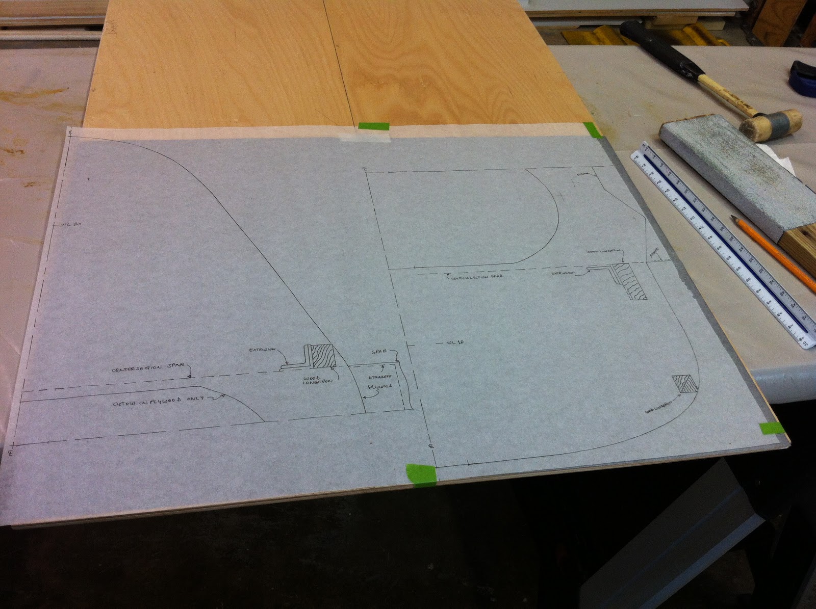 |
| Modified drawings ready to be traced onto the plywood |
Luckily, the plywood sheet I had purchased allowed for enough room to grow, and with some carbon paper I set out to trace my enlarged firewall.
 |
| Bottom half getting done |
When I was done I used a saber saw to carefully remove the firewall from the sheet of plywood, leaving enough margin to account for the jagged edge that such a tool produced.
 |
| Firewall rough cut |
I used a belt sander to quickly and accurately bring the firewall down to the proper size.
 |
| Sanding to exact size |
The inner hole is for lightening purposes, and was accomplished in a similar manner.
 |
| Completed firewall |
No comments:
Post a Comment