Chronicling my Long EZ construction (and a few other things).
Disclaimer
This blog is for entertainment purposes only, and is not meant to teach you how to build anything. The author is not responsible for any accident, injury, or loss that occurs as a result of reading this blog. Read this blog at your own risk.
Changes are inevitable and somewhat expected, the only question is how many times one has to remake something before it's ready for prime time.
Panel #1 had CAD mistakes of my own doing, and needed to be done over. Panel #2 tried to address those issues, plus a few other later concepts I wanted to implement.
An idea I needed to revisit was one I had early on about keeping harnesses separated until the junction box for ease of tracing. This planning decision caused a lot of real estate being wasted at the junction plate/box, the biggest offender being the GNS480 with four lightly used harnesses.
To save space I decided to combine all the wires I needed out of the GNS480 into a single 37 pin Dsub connector, update my wiring diagram, and just grow up.
37 Dsub connector almost fully used now
4 into 1 harnesses
Top two Dsub are now gone
Latest wiring diagram
One other thing I didn’t want to give up was the current single axis autopilot. With the servo, the wiring, and the head unit already installed and working properly, it would be easy to just leave that in… if I could only find a new spot for it.
I thought I'd move the autopilot to where the airspeed indicator used to be
I went with the design above, and set out to machine this even more complicated part. It took me three days of challenging machining, and six setups using up to ten dowel pins at a time to try to maintain alignment and rigidity. The result wasn’t perfect by machining standards, but more than acceptable for the intended purpose, and 100 times better than doing it by hand.
Recycling the current autopilot would be great, at least until I can install the new servos.
The autopilot fit on the new panel was great.
One thing worth remembering is that the autopilot is actually square, not round, so it takes up more space behind the front face of the panel.
Meanwhile, I acted on another good idea, riveting nut-plates behind the panel to be used when mounting the two EFIS.
These small nut-plates will be riveted onto the back of the panel
Cleco clamps hold them temporarily while I determine their exact location
I also use the clamps while drilling the first hole
To drill the second hole precisely, I insert a rivet in the first hole, then drill away.
This tool allows custom precision countersinks to be cut consistently
The rivets are squeezed and the panel is completed
Panel front side
I used the finished plate as a template to drill the holes into the junction box/plate.
This is way faster than setting it up on a CNC mill for drilling
Because of the increased thickness of the instrument panel, I had to counterbore its back side in order to allow the tiny PTT switch to protrude enough to secure it with a nut.
Counterbored the plate about half way down
PTT switch in the countersunk hole
PTT switch protruding just enough to the front of the panel
Here’s ow it turned out…
Panel, junction plate, and 5" (13 cm) standoffs
A view from the "nose cone"
Seems to fit quite well on the plywood panel
Added the goodies for a glamour shot
Of course, I still have to cut into the actual airplane, rip out everything no longer needed, then make sure my new panel fits.
On the software integration front, I am happy to say I have worked out most problems between the GNS480 and the GRT Mini-AP by discussing matters with GRT engineers, and I think I now have a system that should work well in flight.
I’ll attach here a video I made for the GRT engineers to highlight some of the issues I was having. Keep in mind most have been solved as I say in the description.
So much development has been going on behind the scenes, I will need to play catch up for quite sometime.
I have spent every single day off working on one or more aspects of this upgrade, and just haven't had the time to update the blog. Configurations have come and gone, and we are now at instrument panel #3, and junction box/plate #3 as well.
The push has been driven by the goal of flying the plane to Rough River again in 2017, rather than drive the 13 hours there, and for this to happen, I have had to scale back the installation to only the things I need to make the flight, while the rest can be installed after the fly-in.
So let me show you what I call the Rough River configuration…
Rough River panel Photoshopped together
Let’s start with the small stuff first… the annunciator lights.
My idea of a centralized annunciator panel for the airplane's basic functions
I have machined the space for a set of annunciator light right into the panel that will alert me to some of the airplane configurations and possible issues.
The annunciator light are being wired while held in a 3D printed temporary piece
Now, these lights are already on the panel in some way, but they are a bit scattered around, and are not backlit, making one have to search around the panel during the day, and harder to understand what light is what at night.
Lights (aka wiring) are already on the plane, I just need to reuse them for my new panel.
One thing that I deem of vital importance, is the ability to test the lights for proper operation, so that a burnt light bulb will not escalate into a catastrophe (yes, that has happened before, many times).
The "press to test" function being demonstrated
To illustrate the point, let’s contrive an example and say that after the gear lever is placed in the “down” position, the electric motor appears to starts and after a little while it stops but the green light (confirming the gear is down and locked) does not illuminate. What then? Is the gear down or not? It is possible that the gear might be down and locked, but the annunciator light is just burned out.
Ok ok, in this case you have a little window enabling direct observation of the nose wheel, but you get the point, perhaps it is at night and you cannot see well enough to tell.
The point here is that there should be a way to test the light by temporarily powering it directly from the battery.
To do just this, I designed a circuit, machined a circuit board, 3D printed a case, assembled it, and tested it. EZ!
This circuit isolates the different power sources from each other using 1N4007G diodes
Top view of the main board
The traces below will be machined into the copper cladding
A view of the circuit board as it will sit in the 3D printed box
This tight fitting cover will allow easy access to the terminal block's screws
New box and lid right off the "press"
First circuit board being machined on my mini-mill
Broke the end-mill on board #2, and had to fish this test piece out of the trash bin. Hey, it works!
Box #2 vs #1, the design improves.
The PTT (Press To Test) system worked perfectly right out of the box (pun intended), and although I have made four of these boxes already (working on the fifth version), I think it was time well spent to help myself make the right decision on that one dark rainy night…
In the last episode I discussed how the plan is (for now) to bring all the individual wire bundles to a junction box/plate, then do the actual system interconnections on its back side.
Today I will finish the first version of this wiring, knowing full well that it will change soon for a few reasons, one… I’m sill missing the 429 ARINC module, two… I might not get all the functionality I need from this configuration, and three… I’ve never done this before, and I might just blow up the shop.
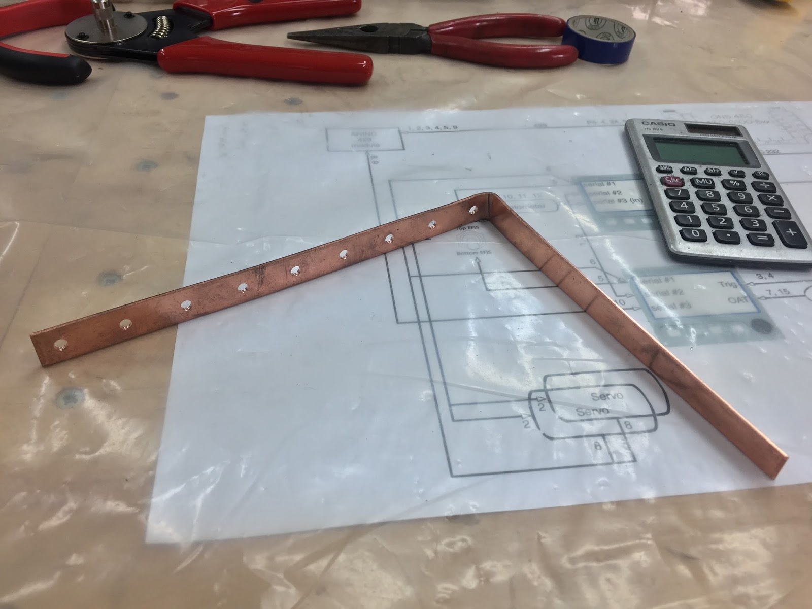
The first thing on my plate was providing a power supply to all devices used, and since this is commonly done through the use of a “bus bar”, I ordered one from SteinAir and started prepping it for panel installation. This was pretty straight forward since I had made the Circuit Breakers spacing to be 3/4” (19 mm), so all I needed to do was drill screw holes every 3/4” on the bus bar.
Drilling my new power distribution ba
I bent the top end in order to clear the big 5A breaker/switch for the servo motors, and provide a way to connect to the existing Essential bus.
The circuit breakers will connect to the holes in the copper bar
After shortening it a bit, I mounted it in place by screwing all Circuit breakers to it.
New bus bar mounted
When the existing Essential bus gets connected to the copper strip, all the CBs will receive power, and trip as necessary if a short or overload is detected within their respective domains.
The second thing I needed to make was a ground return path. I chose to tie all returning grounds together at the back of the junction box, in order to have only one wire exit the panel, and keep it more easily removable.
Ground return path being worked out
All grounds will obviously be tied together here
A ground bar is born
Most of the wiring done (Yep! One pin at a time.)
Now, all I’ve done so far is bringing in power and devices to the junction box, not actually connecting anything to anything else. The hard part will be doing the “smart wiring” inside the junction box (aka… behind the junction plate).
This obviously requires a lot of time spent on each device’s installation manual to understand what connects to what, why and how. I will spare you the learning curve and show you this intermediate diagram I drew up as my guide at this stage of the wiring…
Not the final version yet, but a good start.
If you notice some resemblances to Wade Parton’s diagrams, it is because I’m trying to keep as much commonality as possible with his design in order to simplify possible diagnostic and troubleshooting. Since we both have at least one Mini EFIS, a GNS480, and a TT-22 transponder in common, this makes it easier for him to understand my design choices, and vice versa.
So, with the junction box/plate (JB) removed from the panel and flipped over, let’s start stringing wires based on my schematics.
Junction box/plate removed for initial wiring
This is the actual brain of the operation
I never said it would look orderly. Perhaps I should go back to the enclosed box concept.
After finishing the main wiring of the plywood instrument panel, I did an initial power up test. The "magic smoke" remained inside the radios 😁, so all is well at this point.
Because GRT Avionics hadn't shipped the ARINC module yet, the radio was not able to communicate with the EFIS. Also, to keep things simple at this stage, Pitch and Roll servos were not plugged in yet, though the homemade junction box is already pre-wired for them.
Turning on the switch for the first time
The panel is now a huge step closer to the actual airplane installation, and a vindication of my junction box idea, which so far has performed flawlessly.
Of course none of this would have been possible without some "electrical mentoring" at a distance from Wade Parton, a lot of time digging through the many manuals, and asking “stupid questions”.