Titanium firewall retrofit
While safety is the top priority when engineering an airplane, one of the key players in keeping us safe is the firewall. Although not as glamorous as the engine or the instrument panel, the firewall is one of those parts you definitely want to get right, and while JT’s previous one was made out of aluminum with a heat rejecting paint, titanium is a much better material, making it perfect for this critical function.
We’ve already discussed why the original aluminum firewall needed to be replaced in Fuel Injection Conversion - Part 3 - Engine Removal, so today, I’ll be diving into the process of manufacturing and installing a brand-new titanium firewall. Trust me, it’s not as complicated as it sounds, but it is a bit of a precision challenge.
 |
| Original aluminum firewall looking rough |
 |
| Oil wicked up from the diffuser soaking the now flammable Fiberfrax "protection" |
What’s a firewall anyway?
Why titanium?
It’s also got a very high melting point (around 1,668°C or 3,034°F), which means it won’t melt or buckle under the heat that can come from an engine fire.
Furthermore, titanium is corrosion-resistant, which is perfect for planes that fly through harsh conditions like the saltwater air near the coast where I live.
The Installation Process
This is where things get a little tricky. When you’re installing a new firewall on an older airplane, the holes and studs are already there (on the fiberglass structure), which means you can’t just drill new holes and hope everything lines up perfectly, so I had to get super precise with the measurements.
 |
| Multitude of holes, threaded studs, and L channels projecting from the structure. |
I ended up using a CAD (Computer-Aided Design) system, which allowed me to create a digital version of the firewall and manipulate it until I had the perfect fit. This way, I didn’t have to worry about making mistakes, and it gave me a blueprint I could use for future modifications (or if a future owner of the plane needed to replace it down the road).
To make it foolproof, I used a Cartesian coordinate system on the fiberglass structure to map out every existing feature of the old firewall, then recreated those features in CAD.
 |
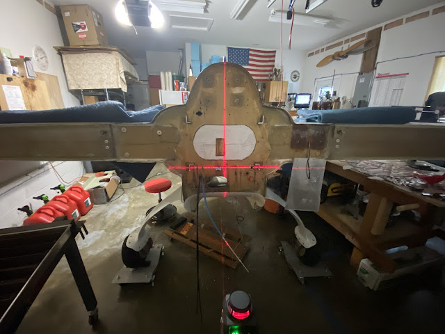
| Using a laser to establish an arbitrary Cartesian coordinate system |
 |
| The coordinate system was then transferred to the structure |
 |
| Here the laser is aimed at the first feature I wanted to record |
 |
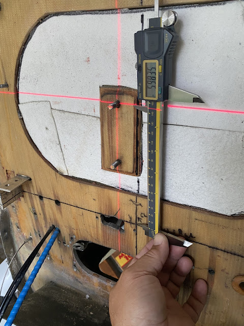
| Measuring the feature's Y distance from the Y axis |
 |
| Training the laser to an existing pass-through hole |
 |
| Recording the location of the fuel supply to the engine compartment |
 |
| Right rudder cable penetration |
 |
| Future location of the engine grounding system |
 |
| One of the three rudder pulley mounting bolts |
 |
| These threaded studs were reused to fasten the firewall |
 |
| This view gives you a good idea of the many measurements that had to be taken |
 |
| And this is the initial resulting virtual firewall |
 |
| The design was enlarged to encompass every structure that needed protection |
 |
| One of many transparencies used to verify the location of all relevant features |
 |
| Working on the feature existing on the wing spar section of the firewall |
Testing the firewall code
This way, I could verify that all the holes lined up exactly as planned. If anything didn’t match, I could tweak things in CAD and try again. I kept this cycle going for weeks, testing and adjusting until I was happy with the fit.
 |
| Many transparencies hanging on the wall, and 3D printed Sharpie holder (in red) on the plasma table. |
 |
| Marking the Fiberfrax using CNC before cutting it saved a ton of time |
Later, I recycled the same file using the CNC plasma cutter to slice through the titanium sheet. A word of caution here, breathing in titanium fumes can be very detrimental to one’s health, so be careful out there!
Cutting the titanium firewall
 |
| Aluminum vs titanium firewall |
 |
| Testing for fit |
 |
| I left the Fiberfrax 1" off the bottom to prevent oil wicking up from the diffuser |
 |
| Started sealing around the perimeter with RTV silicone |
 |
| Nesting the two side protections on a single sheet of titanium (visible below the paper) |
 |
| The 3 part firewall installed |
 |
| There is a 1" overlap between the titanium sheets |
 |
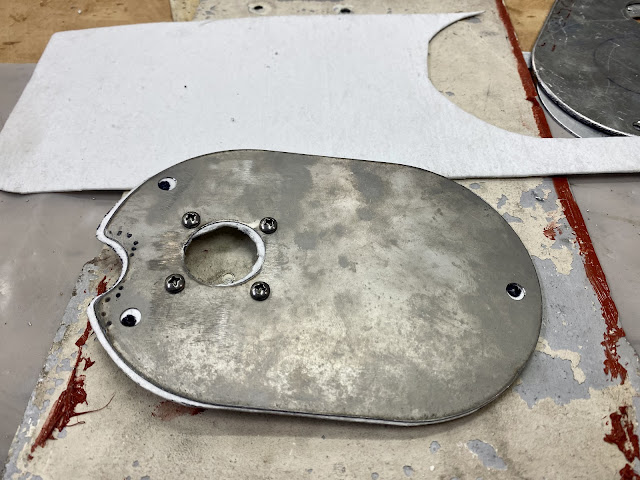
| Cutting the aluminum access cover |
 |
| Cutting the Fiberfrax for the access cover |
 |
| Still dirty from cutting, titanium piece to complete the access panel cover sandwich. |
 |
| Hole cover in place |
 |
| Final look with cannon plug installed (more RTV sealing to come) |
 |
| A closer look |
 |
| Ran all engine monitor probe wires (and a few others) though a single disconnect point |
 |
| The "cannon plug" greatly increase ease of maintenance |
 |
| Firewall completely sealed with engine about to be installed. |
Titanium firewalls might not be the first thing that comes to mind when you think about airplane safety, but they truly play a vital role in protecting both the aircraft and everyone onboard. Installing one isn’t just about slapping a piece of metal in place, it’s a process that requires precision, care, and a thoughtful approach to make sure everything fits just right.
This firewall upgrade project really highlights how modern technology and timeless materials like titanium can work together to make flying not only safer, but also more efficient, and it’s a reminder of how every little detail, no matter how small, contributes to ensuring we get to experience the joy and freedom of flight with confidence and peace of mind.
Cheers!
🍻


No comments:
Post a Comment