"Press to test" circuit for the annunciator light
So much development has been going on behind the scenes, I will need to play catch up for quite sometime.
I have spent every single day off working on one or more aspects of this upgrade, and just haven't had the time to update the blog. Configurations have come and gone, and we are now at instrument panel #3, and junction box/plate #3 as well.
The push has been driven by the goal of flying the plane to Rough River again in 2017, rather than drive the 13 hours there, and for this to happen, I have had to scale back the installation to only the things I need to make the flight, while the rest can be installed after the fly-in.
So let me show you what I call the Rough River configuration…
Let’s start with the small stuff first… the annunciator lights.
I have machined the space for a set of annunciator light right into the panel that will alert me to some of the airplane configurations and possible issues.
Now, these lights are already on the panel in some way, but they are a bit scattered around, and are not backlit, making one have to search around the panel during the day, and harder to understand what light is what at night.
One thing that I deem of vital importance, is the ability to test the lights for proper operation, so that a burnt light bulb will not escalate into a catastrophe (yes, that has happened before, many times).
To illustrate the point, let’s contrive an example and say that after the gear lever is placed in the “down” position, the electric motor appears to starts and after a little while it stops but the green light (confirming the gear is down and locked) does not illuminate. What then? Is the gear down or not? It is possible that the gear might be down and locked, but the annunciator light is just burned out.
Ok ok, in this case you have a little window enabling direct observation of the nose wheel, but you get the point, perhaps it is at night and you cannot see well enough to tell.
The point here is that there should be a way to test the light by temporarily powering it directly from the battery.
To do just this, I designed a circuit, machined a circuit board, 3D printed a case, assembled it, and tested it.
EZ!
EZ!
 |
| This circuit isolates the different power sources from each other using 1N4007G diodes |
 |
| Top view of the main board |
 |
| The traces below will be machined into the copper cladding |
 |
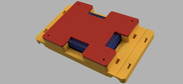
| A view of the circuit board as it will sit in the 3D printed box |
 |
| This tight fitting cover will allow easy access to the terminal block's screws |
 |
| First circuit board being machined on my mini-mill |
 |
| Broke the end-mill on board #2, and had to fish this test piece out of the trash bin. Hey, it works! |
The PTT (Press To Test) system worked perfectly right out of the box (pun intended), and although I have made four of these boxes already (working on the fifth version), I think it was time well spent to help myself make the right decision on that one dark rainy night…


No comments:
Post a Comment