Disclaimer

This blog is for entertainment purposes only, and is not meant to teach you how to build anything. The author is not responsible for any accident, injury, or loss that occurs as a result of reading this blog. Read this blog at your own risk.

Saturday, July 18, 2015

“Tooling up” - sheet metal

Aluminum sheet metal tools

Everyone knows that difficult jobs are made easier by using the appropriate tools, but in the case of sheet metal work this is true ten times over. I would go out on a limb and say that you shouldn’t tackle sheet metal work at all without proper tools, which are expensive by the way, since the risks of hurting oneself, damaging the delicate aluminum, incorrectly shaping parts, or improperly fastening them is very high.

Sadly, the higher cost of equipping a sheet metal workshop was one of the reasons I originally steered away from metal airplanes. With two kids in college, and a B scale airline salary, there was just no room to spare at the time. Ten years later though, with the kids gone and two new Union negotiated contracts under my belt, life has gotten a little easier.

So, why are we even talking about sheet metal anyway?

Well, no airplane is purely sheet metal, composite, or else, rather they all have parts made out of "competing processes". So, many metal planes incorporate fiberglass parts like engine cowls and canopy skirts, on the other hand even the Long EZ has a few things that need to be riveted.

I am coming up with a section of the build where I will have to use rivets, so the time was right to spend some money in new tools, and sharpen my limited riveting skills.

Here’s what I bought…


Various sizes of flush and dome-head solid rivets, Cleco fasteners and clamps.


You might have noticed a couple of things missing from the photos, like rivet gun and bucking bars. For the time being, I decided to go for the hand squeezer rather than a rivet gun, since all my rivets will be located near an edge.

Five years ago I attended a sheet metal construction EAA workshop, but never got to finish the wing section project because we ran out of time. I did however take home the leftover aluminum bits and pieces, so I decided to complete the work in order to freshen up the skills I’ll need to use very soon.


My unfinished EAA workshop project

To make it easier to decide what rivet length to use, I created a small Excel spreadsheet that will calculated automatically exactly what rivet to use in most situation one might encounter, and conform to AC 43.13-1B standards. 


Source AC 43.13-1B chapter 4

The range of calculations for length goes from a 1/16” (dash 1 if it existed) to a 5/16” (dash 10) (second dash in the rivet name). All one has to do is enter the thicknesses of the metal sheets (up to 3) one is trying to join. 

The results are expressed in half sizes, and where those are not available, the next size up would be chosen. In this manner for example one would use a AN426AD-4-5 if he didn't have a AN426AD-4-4.5

The appropriate rivet diameter from 3/32” (dash 3) to 3/16” (dash 6) (first dash in the rivet name) must be chosen based on the application. All 4 diameters are calculated.


Source AC 43.13-1B chapter 4

You are welcome to download it and use it at your own risk... rivet chooser.

If you were interested to learn more about riveting, let me direct you to AC 43.13-1B chapter 4, a fantastic source of aeronautical information, riveting knowledge starts on page 4-31.

In the end, I found out that I still suck at sheet metal work, and that my 2.5 days of total practice time is not enough to avoid making mistakes, but it is just enough to allow me to complete my limited tasks satisfactorily, and that is all I really need right now.


Using the rivet fan to uniformly space out the holes for the rivets

Rivet holes drilled (note the Cleco clamps and fasteners holding the project together)

Getting ready to rivet the structure

Riveting complete


Hinge functional


Thursday, July 02, 2015

Nose and nose gear - part 27

Wheel well mod #2 & #3 (7.1 hrs)

You didn’t think we were done with the wheel well modifications, were you?

Oh no! So far the quest to retract the front wheel completely into the nose has forced well over half a dozen modifications, and more are yet to come. 

Today I will discuss how I hacked part of the recent “Wheel well mod #1” in order to get a proper (if partial) fit, and the process of recovering some of the structure lost in mod #2, with mod #3.

Building the two flox ramps that allowed me to span the gap in the fuselage floor was nearly a complete success, the only issue being that now the wheel well's flange would no longer fit properly, this time due to a different reason.

Allow me to illustrate…


Huge gap caused by the latest ramp build up

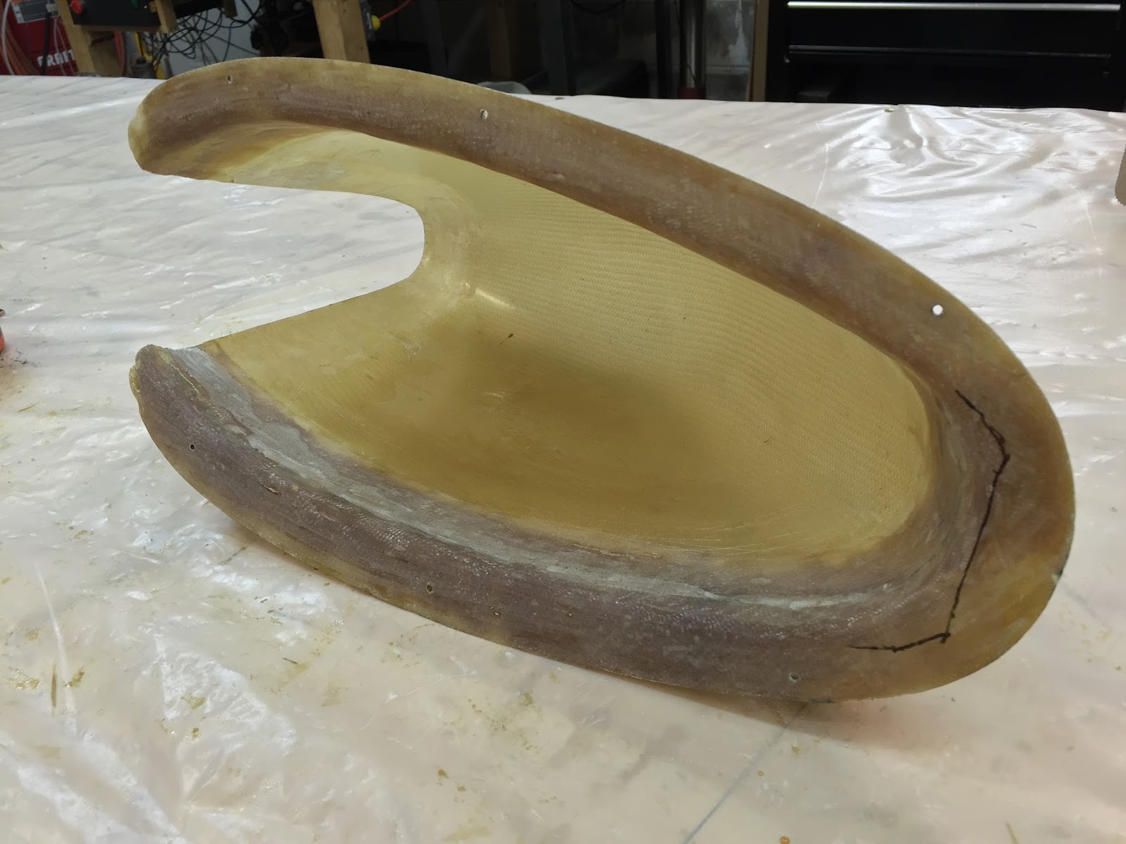
Gap as seen from the wheel side, and wheel well marked for cutting.


As you can see, the ramp elevated the front end of the wheel well to the point that it would no longer fit. My solution (mod #2) was to cut off the leading edge of it, and add a mod #3 to the schedule, where I would rebuild the missing piece to fit the new gap.

And so it was that once again I took the knife to the same fiberglass structure.


Getting ready to cut the forward lip

Mod #2


If we disregarded the gaping hole, I’d say the fit was pretty darn nice.


Good fit with the fuselage floor


So, I attached it to the fuselage floor with flox while the getting was good.


Tape added to keep the flox from getting to the wrong side

Flox on surface to be bonded

Wheel well attached to fuselage floor


I secured it for the night with a few weight.


Usual overnight cure cycle


The next morning I removed the weights, and found the wheel well to be rock solid.


Weights removed and flox cured

Inside view


Beside a little sanding and cleanup, the wheel well was now ready for mod #3, aka the repair of mod #2.


Mod #3 basically consisted in filling the hole I produced when I made the wheel well sit flush. I started by sanding where needed with the Dremel tool.


Getting the fiberglass ready for secondary bonding


I then dammed the hole from below with tape.


Aluminum tape dam to hold the flox, and shape the BID.


My plan was to use two BID plies directly over the hole, and a single ply around the sides (forward only) where my sanding had been a slightly too aggressive.


BID schedule for Mod #3

Going to sleep now


A day later, I removed the peel-ply and the aluminum tape, and checked the results.


"Rock solid Baby!"

Flox showing from below


I think the closing of the hole came out really nice. Now all that was left was to attach the back side of the wheel well to the instrument panel, but first I had to retract the nose gear to make sure I didn’t acquire any new issues.


"Nope, no problems here!"


Cycling the gear went well, so I moved on to masking for the next step.


Trust me, it's going to need it.


With the wheel well so thin, I had accidentally sanded through it in a few places near the edges, so I decided to add one ply of BID all around the intersection between it and the fuselage floor, on the wheel side.

Additionally, I needed to take up the slack for a slight misfit between the wheel well and the instrument panel, so one ply of BID went on that side as well.


Small gaps needing attention

1.5"x14" (3.8 x 35.5 cm) BID tape on the left side with peel-ply on top

More BID tape and peel-ply on the right side

BID and peel-ply on the far end as well

All there was left to do the next day was some cleanup, and the wheel well was finally done.


Job "well" done!

Left side sanded to remove the peel-ply "fuzzies"

Bottom edge of the wheel well trimmed flush to the fuselage floor

As seen from the  cockpit


Thursday, June 25, 2015

Nose and nose gear - part 26

Strut outer cover (13.8 hrs)

You are not going to find the “strut outer cover” anywhere in the plans. As a matter of fact I made up the name as I was writing this post. 

So, what is it?

Well, it is definitely not my idea. 

I am actually borrowing the concept from my friend Beasley, as I am trying to recreate his beautiful gear doors. Where did he get the idea, I don’t know, but he’s a very creative guy, so if he didn't come up with it himself, I'm sure he probably improved on the design.

Anyway, the idea behind the nose gear covers is to try to seal the nose compartment as much as possible, helping to prevent cold air infiltration that could affect the pilot’s legs at altitude (especially during winter), and improve aerodynamics a little.

Most Long EZs have the nose gear strut exposed and flush with the bottom nose skin, but my strut retracts further into the nose than normal, leaving an open slot that I will now try to backfill with foam and fiberglass. And while we are an the subject of foam, today’s story begins with finding enough of it to fill the gap.


Getting some foam to fit the channel

Countersinking some room for NG3

Foam glued to nose gear leg with 5 minutes epoxy

Note the wedge-like foam shape after sanding it flush to the fuselage bottom


I decided to add three BID plies in front of the strut (as seen when extended), and two behind it, sandwiching the leg. One thing to keep in mind is the need to leave enough room for these last two plies below the front three when doing the first layup (with the gear retracted). Failure to account for this could prevent the gear from retracting completely, and perhaps bend the outer strut cover, or even break it.

It turns out that two plies of BID are about as thick as four plies of duct tape.


2 cured plies of BID equal 0.023" (0.58 mm)

4 plies of duct tape equal 0.022" (0.56 mm)


With this in mind, I padded the area where the front layup would rest with four extra layers of duct tape, then I closed all gaps with the wheel well with Plastalina.


4 extra plies of duct tape added to both sides the foam


After cutting the fiberglass, and applying it to the foam, it was off to curing.


I used 3 plies of BID for the front side of the leg cover

"Sleeping beauty"


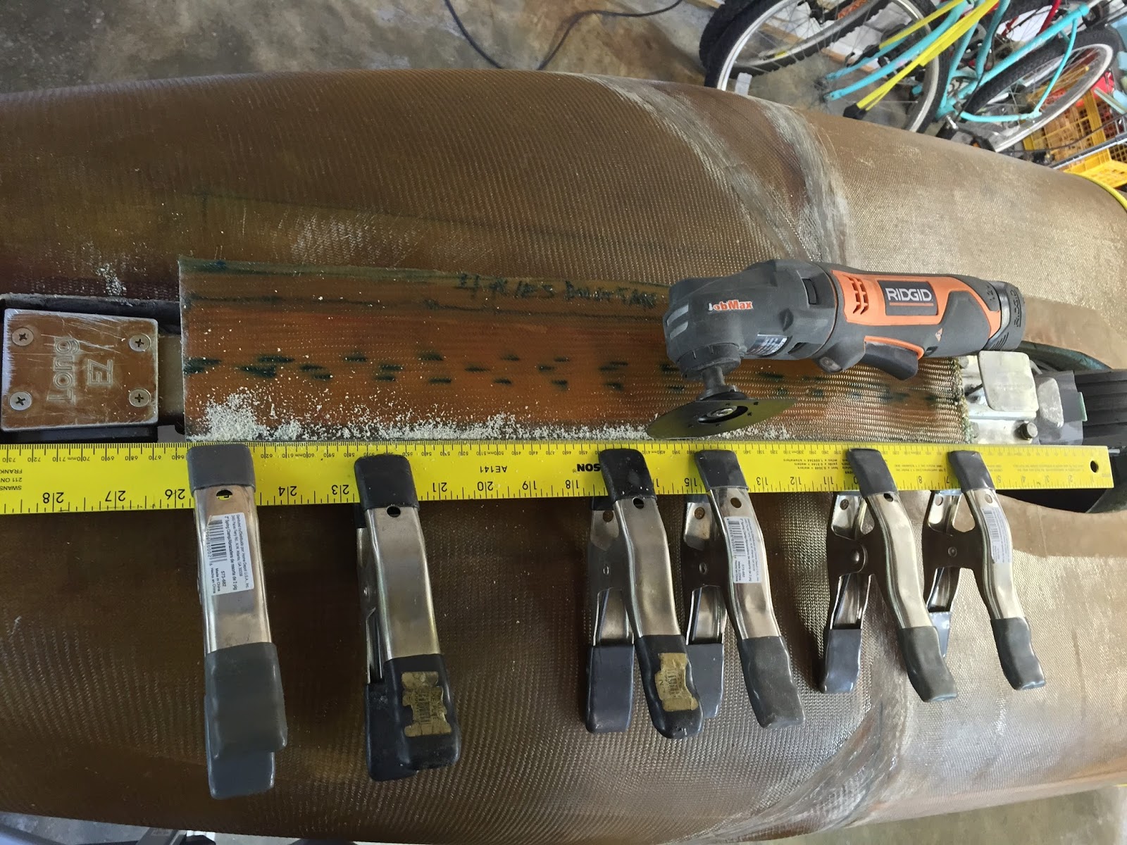
The next day I used a ruler to help me make straight cuts, and leave the cover about 3” (7.6 cm) wide.


Carefully trimming the new cover to size

Gear leg sporting the new cover (front part only)


The Plastalina was its usual pain in the neck to clean up, after which I trimmed the foam flush with the gear leg, and gave it all a good sanding.


Lot of cleanup to do on the back side

Plastalina removed, fiberglass sanded, foam getting trimmed.


All that was left to do was to prepare the two remaining BID plies, add a flox fillet to all 90˚ corners, apply the glass to the gear leg, and let cure.


2 BID plies getting wet

Same 2 plies in position after cutting a pass through hole for NG3 & 4

Letting it rest till the next day


The overnight wait was rough, all I could do was think about whether this leg would fit in its well once again or not, but you won't have to wait, you are going to find out right now.

So, did it fit?

Well… no, not really.

It kind of fit, but it wouldn’t close all the way, leaving a gap between the back side of the strut cover and the fuselage bottom, mostly on the strut end closer to the wheel.


This gap didn't exist before glassing the backside of the strut cover


Apparently the extra 2 plies of BID and the flox transition had swelled up the leg enough to create some tight spots. In some places the unwanted contact was was pretty evident, in others I had to use carbon paper to highlight the issue.


Carbon paper

Face down, the carbon paper is leaving a mark on the strut cover (SC)

Carbon deposits highlight area where rubbing occurs

Carbon transfer on the gear leg after turning the paper around

No need for carbon paper here, it's pretty obvious where the problem was.

More issues

Carbon = problem


The final check was done by slipping a feeler gauge between the gear leg and the strut cover (SC), and sliding it along the length of the strut while feeling for resistance, then sand as needed.


Feeler gauge would stick between the black marks


This process was very time consuming, but in the end it yielded good results, and I was happy with the outcome.


Gap is gone!


Testing the fit of the new strut cover