Working the bugs out of the Z axis
For the life of me, I could not understand what in the world was going on with my mill. I mean, this project wasn’t supposed to be easy, but it should have been achievable. Meanwhile all I’ve had to show for, in exchange for my best efforts, has been a long list of problems to solve, more or less successfully.
The latest mocking came in the form of an alligator-style death-roll of the Z axis ball-screw, rather than the Swiss-like precision movement I was aiming for. Looking for an easy scapegoat I decided to blame myself, due to the way I had tapped the big pulley, freehand.
 |
| "Tapzilla" in action |
I had not intended to tap it this way, but I just couldn’t fit it all under the head of the mill (to help align the operation), so I took a chance, and lost.
The result was so embarrassing that I couldn't even film it, and once again I strongly considered repurposing the mill as a boat anchor. For a moment that is, since I had way too much time, money, and pride invested in this project.
What I decided to do in order to rectify the situation, was to make a steel adapter to go between the pulley and the ball-nut, and to single-point thread everything, thus eliminating the “Tapzilla” alignment issue altogether.
First on the list was the removal of the crooked threads from the pulley. I did this by boring the threaded section out on the lathe to an arbitrary diameter of 1.1” (2.8 cm).
 |
| Boring bar ready to "go to town" on the old threads |
 |
| Threads removed |
Then, I setup the lathe for internal threading using the 16 threads per inch gear train (6.3 threads per cm, or 1.59 mm per thread) I already had in place...
 |
| Internal threading tool ready to go |
... and started threading.
internal threading
I finally had mechanical certainty of parallelism between the thread axis, and the ball-screw.
 |
| Looks the same, but isn't. |
Next, I identified a suitable steel piece from my scrap bucket, chucked it up...
 |
| There is really no such thing as "scrap" in a machine shop! |
... and threaded it.
 |
| I'm getting fairly proficient at this by now |
With the outer thread completed, I mated the adapter to the pulley, and upper flange, and drilled them together to ensure concentricity and alignment of the whole assembly.
 |
| Match drilling the assembly |
Using a boring bar, I precisely enlarged the hole for the internal threading I'd be doing next.
 |
| Precision boring in steel |
Unfortunately, my mini-lathe turned out to be insufficiently rigid for internal threading on steel, and as much as I tried, I couldn’t avoid getting tool and tool-post deflected away from the piece, and unable to do any real thread cutting.
Against my original decision, I opted to bring back “Tapzilla”, but this time it would be centered in the tailstock, once again ensuring mechanical alignment.
 |
| "Oh no! Tapzilla is back!" |
 |
| Freshly threaded steel |
 |
| Concentricity is paramount |
To ensure no more surprises, I drilled and tapped the adapter for two setscrews.
 |
| Drilling set-screw holes in the steel adapter |
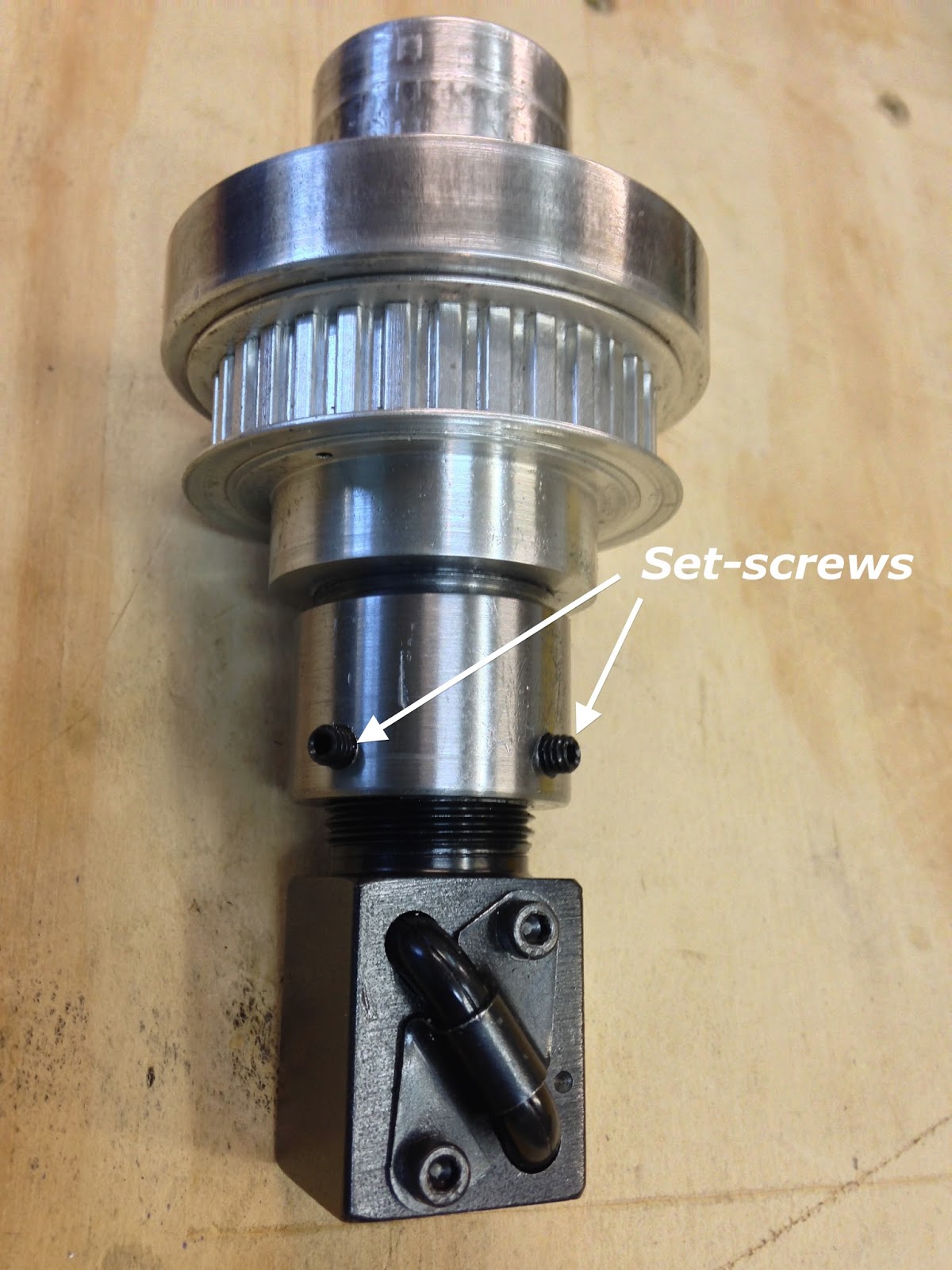 |
| Assembly ready to be mounted |
Finally, I put it all together again anticipating a successful test.
 |
| Bench testing |
But that’s not what I got!
steel adapter thrashing video
Although much better that the first test (the one I didn't tape), this was still an awful performance, and completely inadequate.
Thus, I returned back to square one, once again!
Things just didn’t add up, I knew I was using standard industry practices, and I had been paying very close attention to the smallest of details, yet it had been a “hit or miss” proposition all along, with a lot more initial misses than anything else.
Statistically speaking, it did not make much sense either, 3 out of 3 axes gave me trouble in the ball-screw alignment department, and I couldn’t even fault the design itself, since other people had already successfully used it before me.
No, something else was amiss, and that something had touched all 3 axes in one way or another.
No, something else was amiss, and that something had touched all 3 axes in one way or another.
Of course, I was still number one on the list of probable causes, but I was no longer willing to accept the blame for it. This meant I had to find another “person of interest”.
Removing myself from the list of suspects, allowed me to consider the unthinkable... what if the tap was bent?
It sure didn’t look like it to me, but then again... I did buy it used on eBay! Furthermore, this would also help explain every other issue I’ve had thus far, like the poor finish on the XY plane, due to the alternating up and down movement of the ball-screw (see CNC conversion - part 12), and if all my 15/16-16 threads were crooked, that could have easily introduced binding in all 3 axes.
Brilliant!
Regrettably for me, this new operator-absolving theory needed to be proven correct, and that meant machining a whole new adapter, and single-point internally threading it (in case you lost track, this is the 3rd time I remake this part).
Regrettably for me, this new operator-absolving theory needed to be proven correct, and that meant machining a whole new adapter, and single-point internally threading it (in case you lost track, this is the 3rd time I remake this part).
Since I had just established that my lathe couldn’t internally thread steel, I decided to use 2024-T3 aluminum.
I’ll spare all the machining details here, because they were almost identical to manufacturing the previous adapter, but here goes the new test...
Z ball-nut with 0.125 ball bearings
Much better, right? Yet, you might still have noticed the slight wobble. I think this is due to the small 0.125” ball bearings making for a very loose fit.
Here’s what it looks like after repacking the ball-nut with 0.127” ball bearings.
Z ball-nut with 0.127 ball bearings
Not bad considering it's a 3 foot long ballscrew!
I now felt good enough to throw the whole assembly up on the mill, and take it for a spin (pun intended). Note that the assembly was held together with just a strap, and the head of the mill was attached to the ball-screw with two clamps. This is far from a rigid setup, and was probably a bit dangerous as well, but I put together as a "proof of concept".
I now felt good enough to throw the whole assembly up on the mill, and take it for a spin (pun intended). Note that the assembly was held together with just a strap, and the head of the mill was attached to the ball-screw with two clamps. This is far from a rigid setup, and was probably a bit dangerous as well, but I put together as a "proof of concept".
Initial testing of the Z axis (note clamps and strap)
The time had finally come to bolt the complete assembly to the top of the mill’s column.
 |
| Z axis inner block positioned inside the mill's column |
 |
| Same thing, opposite view. |
 |
| Side brackets bolted to the inner block through the column |
 |
| Ball-screw mount locked down |
 |
| Right view of the ball-screw mount |
Another Z axis test needed to be run (with the clamps still holding the mill’s head).
 |
| Blue clamps holding the mill's head to the ball-screw bottom plate |
Secondary testing of the Z axis at full speed (clamps still being used)
I am pretty happy with the results now, and I will go back and remake every part that was done with the 15/16-16 tap (aka "Tapzilla"). While this tap is probably good enough for things that do not move, like threading a bolt hole, it is definitely not adequate for a fast moving ball-nut adapter.
Also on the list of things to modify, is the aluminum plate connecting the mill's head to the ball-screw. I want this part to be adjustable in X and Y to compensate for small misalignments, but I will discuss this new design further next time.


