More Z axis components, more issues solved, and more tools.
While I wait on the nose gear hardware for the Long EZ, I thought I’d post an update of the status of the mill conversion.
After working on backlash reduction by replacing the balls in the ball-nuts, I ran a couple of quick tests to see how repeatable the X and Y commanded positions were, and shot a couple of videos of the process.
Y axis repeatability test
X axis CNC repeatability test
Next, I started working on the mill’s Z axis left bracket.
This bracket is different from the right one because my mill has a big flange that is in the way, and as a result the bracket has the shape of an upside down “L”.
 |
| Flange on the right side of the mill |
 |
| Modified holes layout |
I started by squaring and surfacing a 3” x 3” (8 cm) blank, then milling the 0.025” (0.063 mm) recess for the top plate. However, something weird happened while surfacing the plate, because the finish had a strange looking cyclical pattern to it. Interesting really, but not what I was looking for, and while acceptable on this part, it might not be on others.
 |
| Top plate recess, and improper surface finish. |
I decided to keep it that way while I would investigate further into its origin.
Meanwhile, I wrote a little G code to cycle trough 4 set of coordinates, and center-drilled, then drilled all the necessary holes to later mount the bracket to the mill column.
 |
| Drilling holes in the soon-to-be bracket |
I used the band-saw to rough the outer contour, and an end mill to finish it.
 |
| Rough cutting the bracket |
 |
| Finished brackets |
On a different subject, you might not know that last year I wrote a couple of articles for a machining magazine. Although they haven’t been published yet, and might never be for all I know, the process led me to strike a few interesting internet friendships along the way. One fellow writer that has actually been published many times is Jerry Prior aka “Ozzie”.
Ozzie was kind enough to let me use one of the modified screen he developed for Mach3 (mill controller software) for use with a probe.
 |
| Ozzie's Mach3 probing screen interface |
I decided that a probing capability will eventually help me save a lot of setup time, so I bought one on eBay, and with Ozzie’s helpful screen I started experimenting with it. I am still far from operational in this respect, but I can almost taste the possibilities.
Here’s a quick and dirty example of something that only takes a few seconds with a probe, but that would probably take me 5 minutes otherwise (I am a bit of slow, I know).
insert probing video
I will probably discuss probing in more details in the future, after thoroughly exploring its capabilities and limitations.
Returning to the strange cutting pattern, I tried all kinds of mill adjustments with no luck, and started to get frustrated by my inability to master this important aspect of machining. The strangest thing was that the pattern was highly localized to the right side of the X axis.
 |
| Surface finish worsening toward the right |
 |
| Another example of bad surface finish |
The pattern actually measured a depth of 0.001” (0.0025 mm), so it wasn’t just a “beauty mark”, instead it was somehow an actual digging action by the cutting tool into the material.
I eventually left on another trip leaving this issue unresolved, but I couldn't stop thinking about it, and I eventually realized that the only thing that could create such a cyclical pattern had somehow to be the ball-screw. So, as soon as I got back home, I stripped the mill down once more for a side to side comparison.
 |
| Things that make you go... mmm! |
Sights and sounds of a troublesome issue
I think what was probably happening was that the ball-screw was binding somehow, lifting the mill table up and then down 0.0005” cyclicly with every turn. Things would get worse toward the right end of the table, as the binding increased where the ball-screw is held.
After another frustrating day of taking things apart, adjusting, putting things back together, and retesting, the solution ended up being to loosen everything up at the same time, GIBs, ball-nut, and shaft bearings-to-table nuts, then tighten them all down a little at a time while running the X axis back and forth, making sure the binding wasn’t reintroduced.
The surface finish is actually better now than when the mill was manual only.
 |
| Before adjustment (top), and after (bottom). |
Here’s a surfacing video of the same fly-cutter that left the wavy pattern on the left bracket, now creating a near-mirror finish...
Not perfect, but nearly so.
All and all, another great learning opportunity, and only a few more white hairs on my head because of it.
The next component to receive attention was the Z axis stepper motor mount...
 |
| Fabricating the stepper motor adjustable mounting plate |
 |
| Mounting plate ready for service |
... and the motor stand-offs...
 |
| Z motor stand-offs before drilling and tapping |
 |
| Working on one Z stepper motor stand-off |
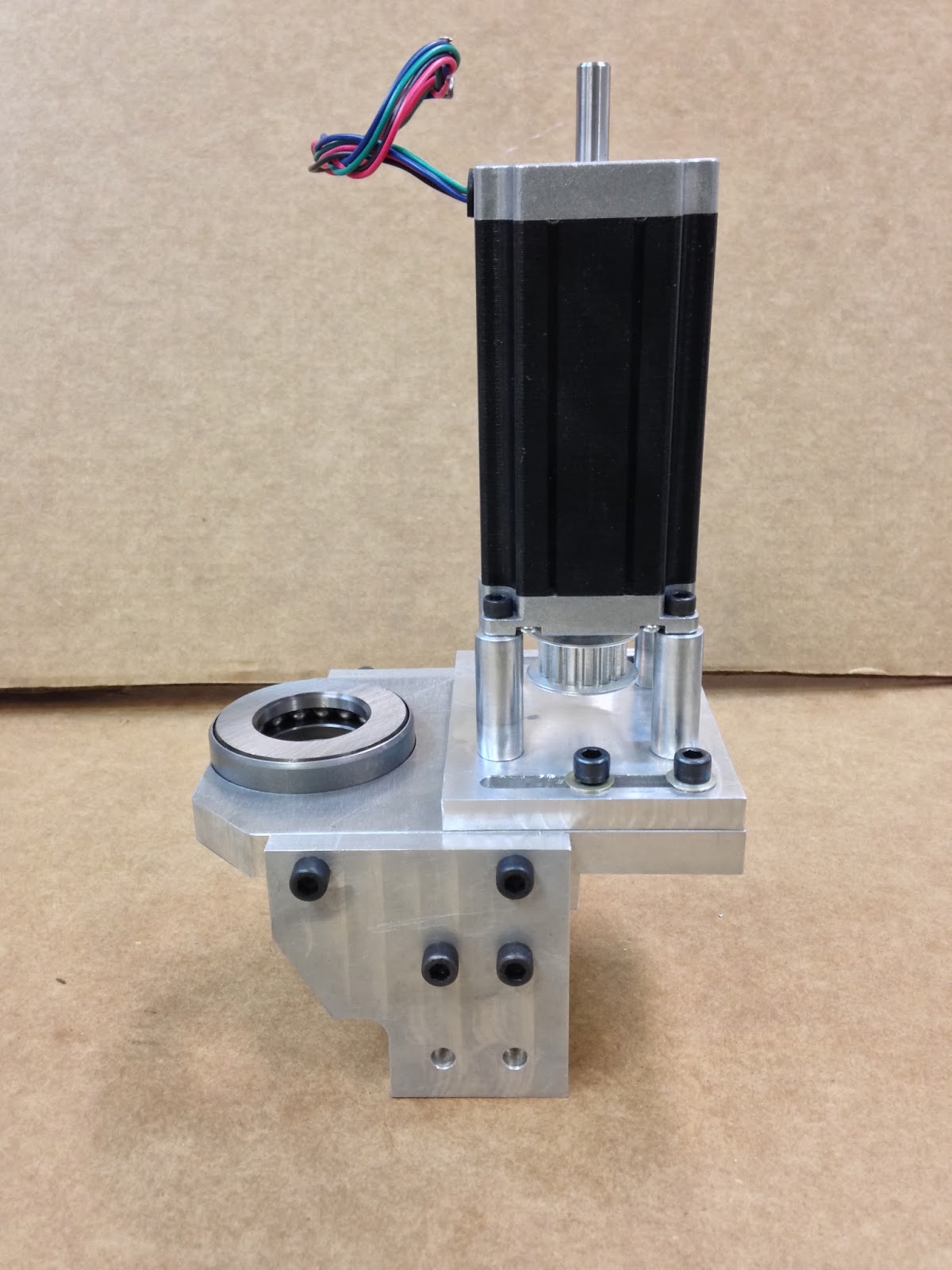
Here they are all together...
 |
| Stepper motor mounted on its adjustable support |
 |
| The small pulley will drive the ball-nut through a belt |
 |
| Flush screws at the bottom were needed in order to fit/slide over the plate above which it is mounted. |
The Z axis spacer was simply a rectangular piece with 2 through holes drilled in it.
 |
| Spacer blank |
 |
| Finished spacer |
The Z axis inner block was much more interesting, as there are tapped hole on the top, and the sides, and they all must end up matching those drilled in all previously made parts. To ensure this, I had to change a few hole locations that did not line up correctly in CAD using the original plans dimensions.
 |
| Inner block with modified drawings |
 |
| Hand tapping the 5/16-18 holes |
 |
| Starting a ¼-20 tap straight, before taking over manually. |
 |
| Spacer and inner block finished |
 |
| Checking for hole alignments |
The ball-screw mounting plate was just too big to be held in my vise, so I had to resort to a different, and more time consuming way to grab on to it, and align it for machining.
 |
| This top plate was too big for my mill, and had to be machined in sections. |
 |
| Straightening the long edge |
 |
| Squaring the short side |
Holes had to be drilled for interfacing with the motor mount, the Z axis spacer, the inner block, and the two side brackets.
 |
| Starting a ¼-20 tap on the top plate |
 |
| Starting the hole for the 2.3" pocket |
The most exciting thing to date was machining the recess hole for the 2.3” ball bearing. This could have been done a number of different ways, like using a boring bar, but I wanted to leverage the 2D CNC capabilities the mill now possess, to make this difficult cut for the third axis.
CNC cutting of the pocket (15 min)
The results of this first CNC project were remarkable (to me at least)...
 |
| CNC milled pocket |
 |
| Inner hole CNC machined wider |
 |
| The pocket's surface is actually much smoother than it appears |
 |
| Pretty nice wall finish with no tool chatter |
Putting it all together for the first time, it was amazing how well the bearing fit in the pocket, and a real relief that all of the holes lined up so well.
 |
| Ball bearing pressed in the pocked by hand |
 |
| Bottom view of the assembly |


No comments:
Post a Comment