Disclaimer

This blog is for entertainment purposes only, and is not meant to teach you how to build anything. The author is not responsible for any accident, injury, or loss that occurs as a result of reading this blog. Read this blog at your own risk.

Monday, April 08, 2013

Washers replacement - part 2

(3.0 hrs)

With the teardown part completed, it was time to put everything back in its rightful place. 

I saved the relative position of the hand-carved, one-off washers, using a marked cardboard. This way I would not wonder why they didn’t fit later, after putting them in the wrong hole.


Every washer was individually fitted to its location, and this is how I kept track of them


I decided to make sure no gap would go unfilled, so I took care of floxing anywhere I though there might be an issue. 


Flox under big washer that will end up on the outside of the sidewall

Flox in proximity of the sidewall holes / gear bracket holes

Most of this flox was squeezed out during tightening of the bolts


A lot of flox was expelled during the tightening of the bolts, but cleanup was pretty easy.


Landing gear bracket back in place


As far as the tightening itself is concerned, I went for 60 in/lbs which is the middle of the 50 to 70 range specified for this size bolts (see my other post). I also used blue Locktite thread locker on the bolts to prevent vibration from loosening them up in the future.

The outside came out pretty decent, and also cleaned up easily. 


Outer sidewall before clean up

Rear lower bracket washers

Top rear bracket washers

After cleaning


I later cut up some leftover pieces of foam to fit, ...


Scraps of foam in place on the left side...

... and on the right side.


... I microed over the bolts, ...


Since I had run out of West System epoxy, I used Easy-Poxy to make this Micro.


... then filled the holes with foam and micro, and used pins to hold it all together while it cured...


These pins were difficult to remove, the plastic heads came right off.

I wouldn't use these pins again, I needed wire cutters and pliers to get them out!

Lots of pins holding the foam scraps in place while the Micro cured


After cure, it was an easy matter of sanding the foam back down to match the rest of the fuselage.

Sanding the Easy-Poxy Micro was not as hard as I had imagined

All ready for final skinning


While I wish I had known about this mod before I put the fuselage sides together, I am glad I found out about it before I glassed the outer fuselage skin. I am happy I did the retrofit now, and I feel confident that I will never see the heads of those bolts again.

I hope this post has helped someone else in deciding whether the amount of work involved in changing the washers is worth it or not. The value of this mod might not be the same in all cases, since many planes have been flying all along without issues, while a few others have encountered some.

As in all homebuilt airplane projects, you, the builder, are the ultimate judge of what you are willing to live with, or sacrifice.


Sunday, March 31, 2013

Voltage regulator - part 4


I finally put together a Pitot testing rig for my truck. Its purpose is to quantify the amount of temperature drop at the tube, due to airflow.


Moving testing rig

Rigs detaches quickly from power supply as well as from the armrest
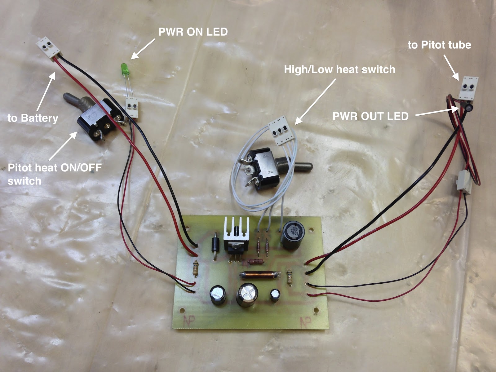
Control panel

Unfortunately the live testing session had to be postponed. The main cause was a lack of volunteers willing to drive me at highway speeds for an hour or two, windows down, at sub-freezing temperatures, while I performed a few tests. 

I just can’t understand people sometimes!

Bringing the car rig back indoor, I setup the first tests to gather two sets of data for the static condition, low heat (ground mode), and high heat (flight mode). These temperatures would be used as reference for the dynamic data, whenever I’d be able to collect it. 

Because of the shortage of volunteers related to the weather, I was forced to come up with less refined testing methodology to get some dynamic data to work with. I decided to put the air compressor to good use by blowing air at 30 psi over the hot Pitot tube, and measure the induced temperature drop. 

Sadly, one of the drawbacks of polishing the Pitot tube to such a glossy mirror finish, is that my IR thermometer refused to work with it, and I had to go back to using the AC pocket thermometer, whose upper limit reaches only the low 200s (℉).


Simulating inflight airflow cooling action


My Voltage Regulator design has two settings, one is low heat (low voltage), the other is high heat (high voltage).

Here's my reasoning behind the 2 settings...

When the pilot turns on the Pitot heat on the ground, the low heat circuit is activated. This setting warms up the Pitot tube verifying the system is functional, and the low heat won't damage the foam in the nose structure, even without airflow.

During the takeoff roll, an airspeed switch (or EFIS command) would activate the high heat circuit, providing enough "juice" to keep ice from forming on the probe. The pilot would not have to remember to turn it on, because it would be automatic. A green LED for ground mode would turn blue for inflight mode, as status confirmation.

Back on the ground, the pitot heat would revert again to ground mode automatically during the landing roll, preventing damage to the nose structure should the pilot get distracted and forget to turn the system off. 

In ground mode, coming accidentally in contact with the probe would not create a burn hazard, due to the mild temperature involved (around 120℉).

Back to the tests, here are the 3 data sets I recorded combined into one graph. 


High heat, low heat, high heat and airflow versus time


Now, let’s try to make some sense of it!


I'm satisfied with this curve


It would appear that the ground-mode does a good job of preheating the tube, without making things so hot that someone could get burned, should he/she get in contact with it. It is a very shiny object after all! 

In the retractable version the pilot would want to retract it soon after shutdown, so the potential for leaving some skin on it is there.


I'm not very excited by this curve


The air-switch activated inflight-mode seems to have a good max value, but is a bit slow at ramping up the temperature. 

The real problem in this instance could be when encountering icing conditions right after takeoff, with a Pitot heat that might not be spooled up yet, and the added airflow-induced temperature drop would just compound this issue.

Ideally, I'd like to see it reach max temp as fast as possible, then stay there indefinitely.

To do that, the Pitot needs as much power as possible right at takeoff, when it is still relatively cool, and has a harder time getting warmer because of the airflow.


Ideal Pitot heat spool up


I smell a potential issue here, but let's add some airflow and see how that affects the maximum temperature reading.


Heat loss due to airflow


Looking at how much, and how quickly, the core high temperature drops with airflow (orange line), it seems that it would probably take a long time once airborne for the Pitot to even reach the 110 degrees plateau, if ever! 

My guess on this drop was around 50℉, I certainly was not expecting nearly 130℉!

I could probably get a little more power out of this voltage regulator, but that would also raise the max temperature. Given the amount of temperature drop caused by the air movement though, I feel that there is some room to expand upward without bumping into the foam heat-limitations (around 170ºF).

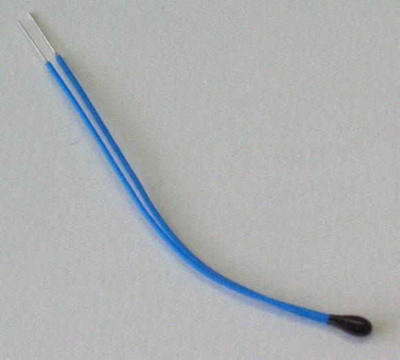
A more targeted way to steepen the initial heat ramp without having max temperature issues, could be using a control resistor that can change its value based on temperature. A properly sized Negative Temperature Coefficient (NTC) Thermistor could be buried (for lack of a better term) into the Pitot tube, and from its vantage point it would be exposed to the same temperature changes as the inner tube. 


One kind of Thermistor


Inflight, with the tube temperature decreasing due to the increasing air flow, the NTC Thermistor would increase its internal resistance. Utilizing another set of wires pulled through the back of the retractable Pitot (or the side of the fixed one), the thermistor could control the output voltage of the Voltage Regulator, increasing the voltage when the temperature goes down, and reducing the voltage as a high temperature is reached.

In a system of this kind, you would see a high initial amperage draw, I'm thinking around 5 amps with this circuit, with a time to max temperature in the order of 2 to 3 minutes, then a gradual current reduction to very low values as the target temperature is achieved. Heat would be produced on-demand as conditions change, so you would expect a fluctuation of this current draw over time, corresponding to the changing OATs.

I’ll be testing the thermistor based circuit board soon, but it is very possible that a more powerful circuit might be necessary. 

Anyway, it seems that more R&D (i.e. time & money) might be necessary once again, and my shaky machining skills could finally get pushed to the breaking point.


Monday, March 25, 2013

Washers replacement - part 1

(8.5 hrs)

Apparently, sometimes in the '90s, someone came out with the idea of using big washers (AN970-4) on landing gear mounts. The washers I’m talking about are on the outside of the fuselage, underneath the foam.

The reason for the modification was that the original washers (AN960-416) tended to crush their way into the wooden longeron over time, and cause a loose feeling in the main landing gear.


Central States Association January 2013 newsletter


The reason I did not want to replace mine, was purely due to the amount of work involved. It was going to be a big pain in the rear, and I was afraid I might end up damaging something else in the process. 

Now, most of the people I talked to never heard of this problem before, so it’s probably not a very common issue. Nevertheless, because I still had the extra thin washers out there (AN960-416L) by mistake, I felt that my safety margin was heading in the wrong direction.


From left to right: AN970-4, AN960-416, AN960-416L


In light of the latest news (for me at least), I decided to finally take action, and as you’ll see, the process was not enjoyable by any stretch of the imagination. Cutting into my work was stressful, but luckily for me, I had not yet skinned the outer fuselage, so the removal of the washers was not as bad as it could have been.

I made a 36 minute video of the removal of the left side washers, that you can see it here...


Long video - ALERT!!


... or, you can look at the pictures I took while working on the fuselage.

It all started with cutting a nice hole into the very foam I spent so much time caring for, and shaping.


Doing the unthinkable!


The goal is to uncover the head of the bolts...


Found them!


... which are encased in micro...


More bolts under there...


I just used this little tool as a chisel, to knock big chunks of micro off the bolt.


Makeshift chisel


Similarly, I removed foam and micro from the other buried bolts.


More digging

More Micro encased bolts

These bolts need to come out


Removing the bolts was very tough (just look at the video above), requiring heating, and banging with a rubber mallet. 

Once the bolts were off, I was able to trial fit the new washers, and had to shape them on the grinder, and smooth them on the belt sander, since they were too big to play nice with each other.


Modified big washers

Almost got away with it here!

Lots of shaping with these two


The last step was to sand everything down, and beef things up with a few extra plies of BID.


Fresh epoxy

Beefing up the structure

A little peel ply

All finished up for the day


Once it all dries up, I will drill the holes once more, reinstall the gear mounts, bolt it all back together, and replace the missing foam.

All in all, I am really glad I did this. I would encourage anyone who has not yet skinned the fuselage to make the switch, since it is very doable at that stage. If you wait until your plane is on its gear, it might just be too difficult.


Wednesday, March 13, 2013

Voltage regulator - part 3


Let’s recap for a minute the progress of the voltage regulator circuit board.

I started out with a proof-of-concept “bread board” circuitry, on which I tested the validity of the idea.


Original proof-of-concept board


Later, I conducted full power tests on the heating element using components mounted on a blank board.


Full power testing board


Now, I will take you through the process of making the actual circuit board. This board will reside inside an enclosure, and supply metered power to the heated probe.


Final(ish) design


There are a number of computer programs that can help with designing a printed circuit board (PCB), in reality they are not really necessary, but they are nice to have to help narrow down the final design. 

Right below are some of the programs I checked out. I will not say which one I used, you can pick whichever you like best, or find a better one online.

Express PCB (Windows)

Eagle PCB Software (Windows) 

Fritzing (Windows, Mac and Linux)

My design for a voltage regulator has a high setting, and a low setting, selectable via a switch (for now). It is meant to be used in ground mode (low heat), and flight mode (high heat). These values should be pretty close to the final ones, but more testing on Wade’s Pitot will have to confirm them. 


My board design


In the early ‘80s I used to make my own circuit boards by rubbing the back side of transferable patterns onto copper boards. These were later dipped in acid to dissolve the uncovered copper, leaving only the desired traces. 

Today’s methods are still basically the same, but the quality of the final board can be greatly improved by enlisting the help of photographic style processing. Like in the old days, it can still be done at home as I will try to demonstrate.

Back to the PCB design, it is necessary to finalize the design, be it computer based or hand drawn, before proceeding to the next step. 

Out of the various methods out there, I chose to use a copper board coated with a substance called “photo resist”. I’m not  exactly sure what it’s made of, but whatever it is, the important thing is that it is sensitive to light, and I will use this property to transfer my design onto the board.

I ordered a pre-made kit from www.jameco.com (item #2113244). This kit contains two circuit board with photo-resist on them, one big bottle of ferric chloride, and one little bottle of board developer solution.


Board creating essentials


Now, all of these liquids are really really BAD things to get in contact with, as an even cursory reading of their spec sheets will show, so a high level of protection and ventilation is a must.

The steps to the process are:

  1. Print the circuit on a transparency
  2. Lay it on the photo resist side of the copper board
  3. Expose it to bright light for 8 to 10 minutes
  4. Develop the circuit image onto the board  by dipping it in a 1 to 10 solution of developer and water
  5. Rinse the board in cold water
  6. Immerse the bard in a 1 to 1 solution of ferric chloride and water for 20 to 30 minutes
  7. Rinse the board in cold water
  8. Remove any trace of photo resist with nail polish remover
  9. Drill the holes for the components

Done!


Transparency printed at the FedEx store for $0.45


Transparency trimmed and laid on a picture frame $2.00


Using an halogen lamp to expose the photo resist on the copper board


I used clear tape to secure the transparency to the board at the corners


You can see the circuit developing on the PCB


I should have probably used a regular light bulb, or leave the board in the light longer, because a part of the circuit vanished from the board during development, and other parts were a bit thin.


Circuit fully developed (sort of)

I corrected that with a few strokes of permanent marker.


Black marker used to rebuild some of the traces


PCB bathing in ferric chloride


Ferric chloride eating away the copper from the board


Process almost complete


Etching process complete


PCB done! Photo resist and black marker removed with nail polish remover.


PCB nearly ready to go to work


finished PCB ready for testing


I think I might "massage" the design a bit to produce a smaller PCB, there seems to be a lot of wasted space on the board, but overall I am satisfied with the final product.

I will be looking for a suitable enclosure next, and the final size of the PCB might depend on what box I can find to house it. A smaller PCB is better to a degree, but larger one is easier for me to solder.