Disclaimer

This blog is for entertainment purposes only, and is not meant to teach you how to build anything. The author is not responsible for any accident, injury, or loss that occurs as a result of reading this blog. Read this blog at your own risk.

Monday, June 25, 2012

Epoxy 102


Un-Gelling the hardener
Before I left for my latest trip, I ran into a problem when I tried to use the E-Z Poxy hardener. It had turned into a big lump of Jell-O, and was basically unusable. 

Looking into the hardener canister

This had me a little concerned since this stuff is not cheap, and it's only 4 months old. 

I had read that this might happen if the container is kept in a cold environment, but this year we have had an unusually warm winter, and my shop never got below 50℉ (10℃), nevertheless... there IT was.
Tracy, at Aircraft Spruce, hinted that heating up the hardener to 120℉ (49℃) would probably return it to usable conditions. 
Still skeptical, and expecting the worst, I decided to give it a try with a small scale test on the little container I employ for ratio testing, itself afflicted by this apparently infectious condition.

Coagulated hardener

You can see the video I took of this experiment below.


UPDATE #1:

I heated up the canister of hardener to 120℉ as directed, and it worked beautifully.


Heating up the hardener to 120℉

Compare the way it looked in the pictures above, to the way it looks now.


UPDATE #2:

CP 29 page 5 states that this temperature should have been between 160℉ to 190℉  (71℃ to 88℃). 

Check out Epoxy 103 for more details


UPDATE #3:

Apparently the resin can crystallize as well. 


Resin solidifying

Solidified resin (later melted back with heat)


Just follow the procedure highlighted above.


Saturday, June 23, 2012

Ch. 5 - Fuselage sides - Part 3


Shaping the fuselage sides (9.8 hrs)
With the second fuselage-side-panel completed, I took some time to sand them together, ensuring they are identical, then I moved on to marking the location of all the bulkheads on the sidewalls.

Two fuselage-side-panels stacked for sanding

This was pretty simple to do, as all the dimensions are clearly stated on the drawings. As far as the complex geometry of the landing gear support structure, located behind the rear seat, I had to resort to copying the drawing, and locating important intersections with my paperclip method.

Transcribing landing gear mount structure details

Gear mount structure outline

Here’s a look ahead to how it will all fit together, hopefully.

Test fitting

The space between the wood pieces will be filled in with foam, then the whole support structure will be glassed over. Enough plies will be laid, to strengthen the attaching point for the gear mount.
Another item on the agenda for today was digging out a circular depression next to where the joystick will go.
The purpose of this is to provide some room for the pilot’s knuckles as he hand-flies the plane, especially during full right stick deflection (I plan on lots of those). This is not a big concern in my case, because I have an extra inch of width right there, nevertheless I think it looks cool, and might remove a gram or two of foam.
I decided to go high-tech with my foam removal approach, reasoning that sanding blue foam looked a lot like hard work. Besides, it gave me some excuse to try out some router accessories that I bought a while back, but never used.
I decided to proceed in small increments, trying real hard not to make a mess of things. First I cut a circular groove 1/2” deep, to make sure this circle making attachment actually worked.

I can't believe this thing actually works!

Encouraged by the results, I switched to a 45˚ edge cutter, minus the bottom roller bearing. I raised the cutter to make sure the bottom of the tool would not dig deeper than the 1/2” groove I just cut.

Shaping the sloping sides

It wasn’t the perfect tool for the job, but it was the closest to it, and left a little edge that I could cut smooth with a razor blade later.
So far so good.
Finally I used a cylindrical(ish) cutting tool to remove all of the inner circle foam. Unfortunately for me, I forgot to lower the tool stop back to the 1/2” mark, and so I took this beautiful, as well as too shallow and useless cut next.


Basically, I ended up with 1/4” of foam left to cut by hand, which turned out to be as painful as I had imagined. The real shame is that it could have really been an awesome looking depression. Oh well!


Moving on!
The last thing I did before packing it up for the night, was floxing the stiffeners to the longerons. 

Stiffeners floxed to the longerons


That would normally be a pretty easy thing to do, but this time I had to disassemble the hardener side of my pump and clean it up with Acetone, as I couldn’t get much out of it anymore. 
Somehow the hardener had turned into some sort of sludge, and the ratio between hardener and resin had dropped from 44 to 100, to 4 to 100.
Not good at all!
This should emphasize the need to do a ratio test before each job, especially if the pump has not been used in some time.
Opening up a brand new can of hardener revealed a similar situation, and its content couldn’t even be poured out. When I called Aircraft Spruce, Tracy told me to heat it up to 120℉, and it should become like new again.
I remember reading about this somewhere, but I guess I’ll find out whether it works or not when I get back, because I’ve got to get on the road tomorrow.
I’ll try to take some photographs of the gelatin-like epoxy, and post an update on the results of the heating technique. 


Thursday, June 21, 2012

Wet-Micro foam bond demo


Braking the bond
In case you ever wondered how strong can the wet-micro bond between foam pieces really be, I have decided to show it to you.


Maximize the video and select a higher resolution for better viewing.


Wednesday, June 20, 2012

Ch. 5 - Fuselage sides - Part 2


Fuselage: the other side (6.0 hrs)
Today I measured and cut the panel I made yesterday, and I also glued the second fuselage side. 

Fuselage bottom traced onto the foam for cutting


One thing I have learned about cutting foam with a razor blade, is that it is sometimes difficult to make a vertical cut consistently. I decided to combine the blade with a machinist square, held together with a C clamp.

Home-spun foam slicer

Foam cutter business end

Foam cutter at work


I know what you are thinking, but this thing really rocks! 


It makes slicing foam with precision a piece of cake, and gives you a beefy something to hang on to, instead of the skinny sharp blade.

Check out the quality of the cut below.

Nice, even, on the black line, orthogonal cut

Sidewall ready

Of course, I couldn't resist the opportunity to set up the scene for a photo op.

A sign of things to come...


Next, I got started on the other side, but I only had one complete foam panel left, and a lot of smaller pieces that did not fit very well.  I had to sand them square, and assemble them into a contiguous piece. This process actually took a lot longer than anticipated, and generated a lot of blue foam dust that ended up everywhere.
I eventually got all of the mosaic pieces lined up long enough to tape the seams.


Then flipped it over...

Foam sidewinder


And glued it, just as I did on the other sidewall.

Weighing things down


As soon as the micro cures, I’ll trim it so that both sidewalls match.


Tuesday, June 19, 2012

Ch. 5 - Fuselage sides - Part 1


Foam board magic (5.0 hrs)
I have finally arrived at the first substantial part of the construction, and part of the reason why I built the “monster-table”.
The fuselage sides are way too big to be made out of one single piece of 3/4” thick foam, so I will have to glue at least 3 pieces together, and cut as necessary.


Blue foam and wood longerons


The upper part of this drawing shows the blue foam already cut to dimension, while the bottom shows the assemblage of foam, and wood longerons, and the location of the bulkheads.
Because the top longeron will become a very important reference point later on, it is necessary that the foam that attaches to it, be as straight as possible to begin with. I used a straight edge to line up the foam boards while I glued them.


Making sure this edge is straight


Once again, I used some duct tape in the back of the seam, so that I could spread the joint apart without losing the careful alignment.


Next, I whipped up a new batch of wet-micro. 


Wet-micro


The reason it looks so white, is that I used leftover West epoxy instead of the usual E-Z Poxy. This is not a structural connection, so I elected to go with the fast curing stuff, in order to get this project back on the road.
Anyways, like I was saying, I whipped up some wet-micro, and filled the joint with it.


After unfolding the foam boards, I cleaned up the excess.


Then, I used every heavy item I could find, and weighted down the boards to allow them to dry as flat as possible.


Using every heavy object in sight to keep the foam down


Later, I flipped the foam boards over and ripped the duct tape off.


Taking off the band-aid


Needing more foam to reach the 103” dimension, I cut the width in excess of 21”.


Excess foam trimmed off


Then cut a piece off of that, and glued it in the back of what is now a really big foam piece.


While waiting for the wet-micro to set, I decided to start cutting the wood for the longerons, stiffeners, and gear mount build-up area. 
Oddly enough, while laying out the drawing on the wood, I kept coming up with some misalignments in LWX. 
So, I decided to verify the angles on the plan’s drawings, and I noticed that one of the angles is incorrect. It was probably just rounded down to 35˚ for simplicity, but the correct angle should have been 37.5˚.


atan(1.0/1.3) = 37.57˚


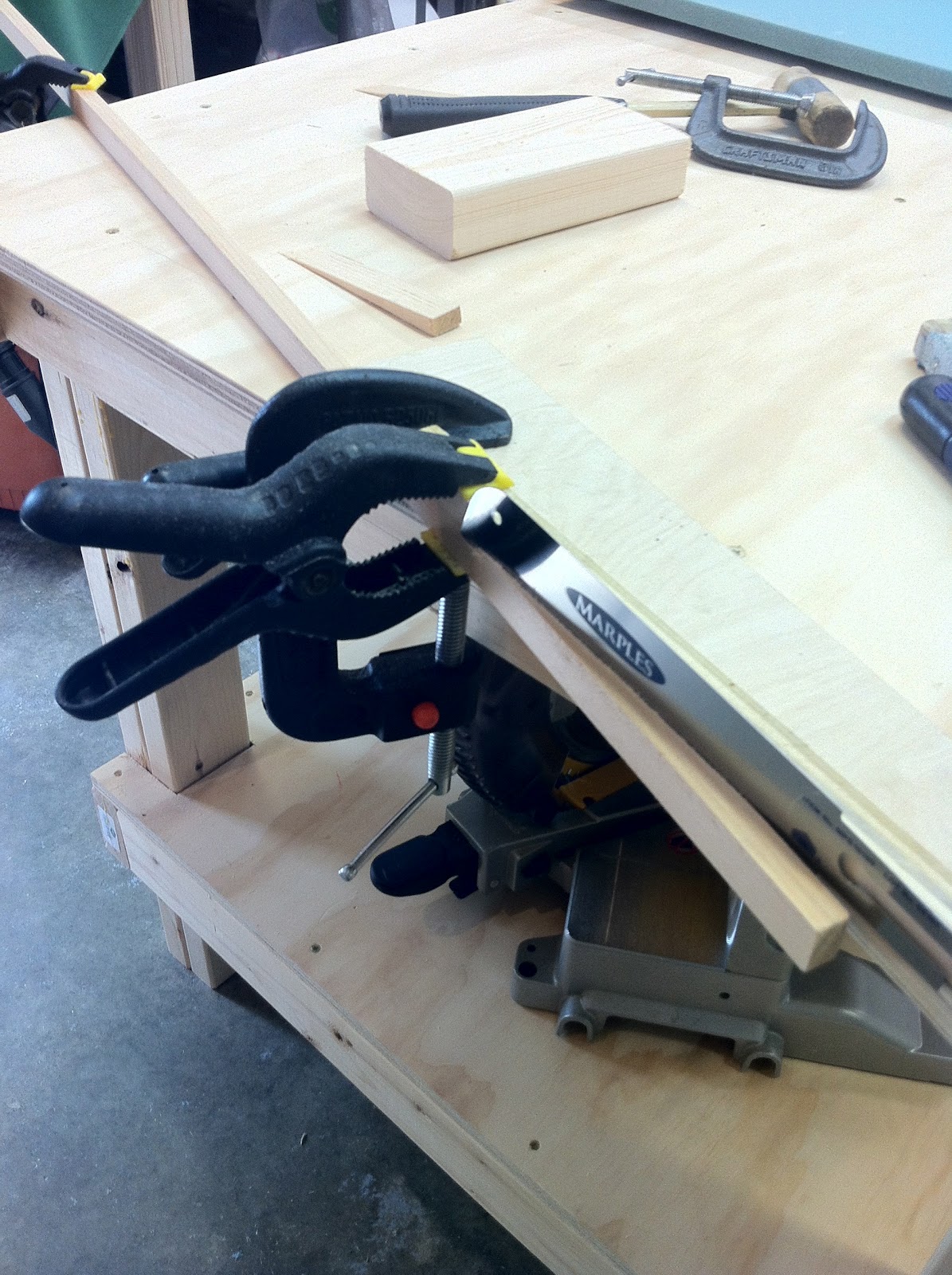
Setting up a cut like that on the miter saw is impossible, because one would have to cut the complementary angle 52.5˚, while the saw only reaches 50˚. To get around this limitation, I cut a 2.5˚ slope in a piece of scrap 2” x 4”, and used it to back up the part I was trying to cut. 
With the miter saw set at its maximum 50˚, and the 2.5˚ slope cut into the scrap wood, I was finally able to line up my blade with the target cut-line, and easily produce a 37.5˚ angle.


Note the shadow of the blade lined up with the cut line! :-)


The opposite end of LWX, as well as LWY, were easy 45˚ cuts. 


Producing the 103.5” longerons was as easy as measuring, and cutting. The stiffeners though were a bit more involved. First, I had to rip a 1” piece into two 0.4”.


Ripping him a "new one"!

Two "ones", perhaps?


Then, I had to shape them at an odd 4.6˚ by hand.


Are all these weird cuts really necessary Mr. Rutan?

This thing could put an eye out!


So, this is as far as I’ve gotten today.


This is as close to a "Long EZ kit" as it gets.


In the next session, I will shape the fuselage side I made today, and try to glue, and shape another one as well.


UPDATE

I should have left LWY a couple of inches longer because I ended up having to extend it later. 

I have heard from a few builder friends that they ran into the same issue as well, so I'd suggest leaving it long and trim it at a much later date.