Wing attachment points (45.0 hrs)
"How many bolts does it take to mount a Long EZ wing to the fuselage?"
"Three."
Yep, you read it right, only three bolts are needed to keep each wing attached to the center-section spar, and the wing bolts attachment points (aka metal plates) are all installed in the first foam block (FC1).
 |
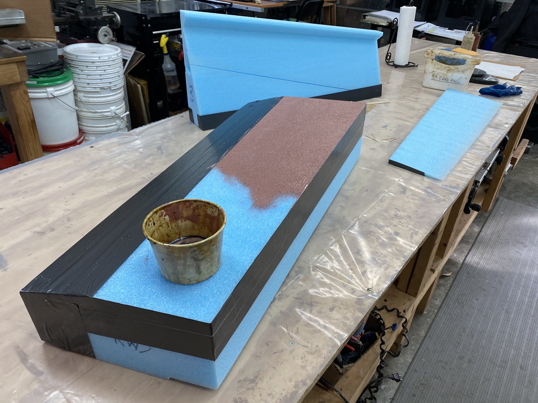
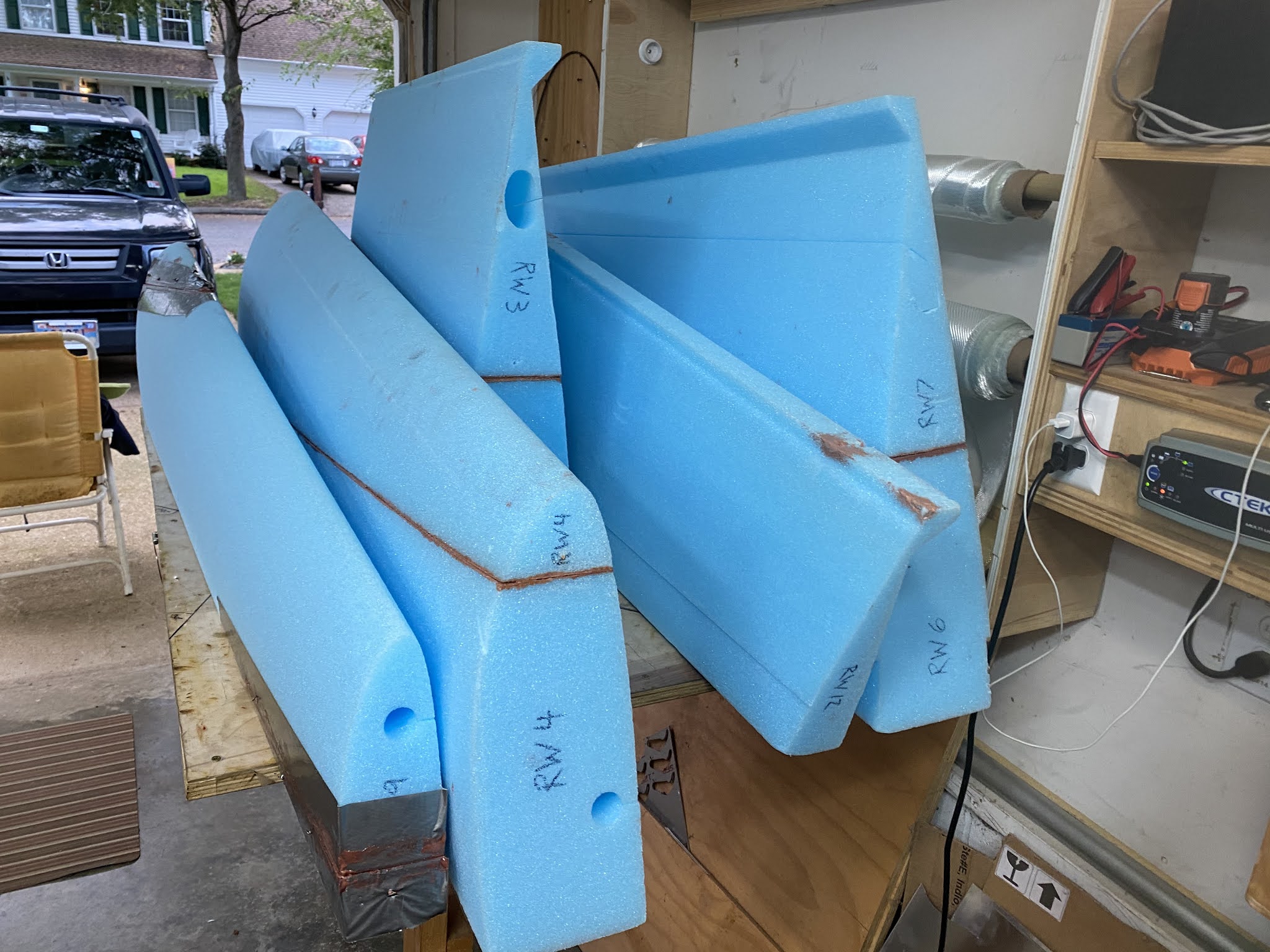
Eureka CNC plans broken down by major foam blocks
|
Two of these bolts are accessed through two small dedicated depressions cut into the top and bottom of the wing, and one from the wing root pocket.
 |
| Using JT to illustrate the location of the wing's top bolt... |
 |
| ... and the wing's bottom and inner bolts |
The plans will have you do the work of creating these pockets with the foam blocks already in the jig, but it is much easier to do it before glueing FC1 to the rest of the wing.
Let’s work on the root pocket first, then we’ll do the other two.
This process involves slicing off a part of FC1, hollowing it out, then glueing it back to FC1, then installing the first one of many metal plates.
 |
| Marking the cut line on the wing root foam block |
 |
Using two nails on the black line as guides for the ruler
|
 |
| Clamped one ruler on the wing foam top, and another one on the wing foam bottom. |
 |
| Using the rulers as guides for the saw |
 |
| This will become the wing root pocket |
 |
| Using the rulers as guides again |
 |
| Cutting off the critical 0.6" (15 mm) dimension |
 |
Front face to be reattached later, 0.6" non-critical perimeter marked in black.
|
 |
| Creating the wing root cavity |
 |
| The inner piece of foam will be reused to stabilize the now delicate foam perimeter |
 |
Front face reattached to the perimeter foam, curing around the inner core
|
 |
| Wing root section with micro, in preparation for getting reattached to FC1 foam block. |
 |
| Wing root section curing after being reattached to FC1 |
Talking about metal plates, I had already made most of them years ago when I was working on the center-section spar, but a few of them weren’t mentioned in the spar chapter, so I had to make some new ones.
 |
| Two LWA4 ¼" (6.35 mm) 2024 Al plates, and two WI8 0.016" (0.4 mm) 2024Al sheet |
 |
| Etched then Alodined the metal parts |
We will use these a little bit later. First we have to create the depressions for the outer two wing bolts, one on top of the wing, the other on the bottom, then glass them.
 |
| I often colorize the plans' photos in the blog to make them a little easier to understand |
Unfortunately the depth of the two depressions are not only different, but also decreasing the further back one goes due to the slant of the wing profile.
 |
| Measuring the deepest part of the slot (gray= metal, blue = foam) |
 |
| Bottom slot is 0.030" (0.76 mm) shallower |
The floor of the depression however is perpendicular to the front face of the foam block, so with a little ingenuity (thanks Ary) it is possible to cut the foam as in the plans.
 |
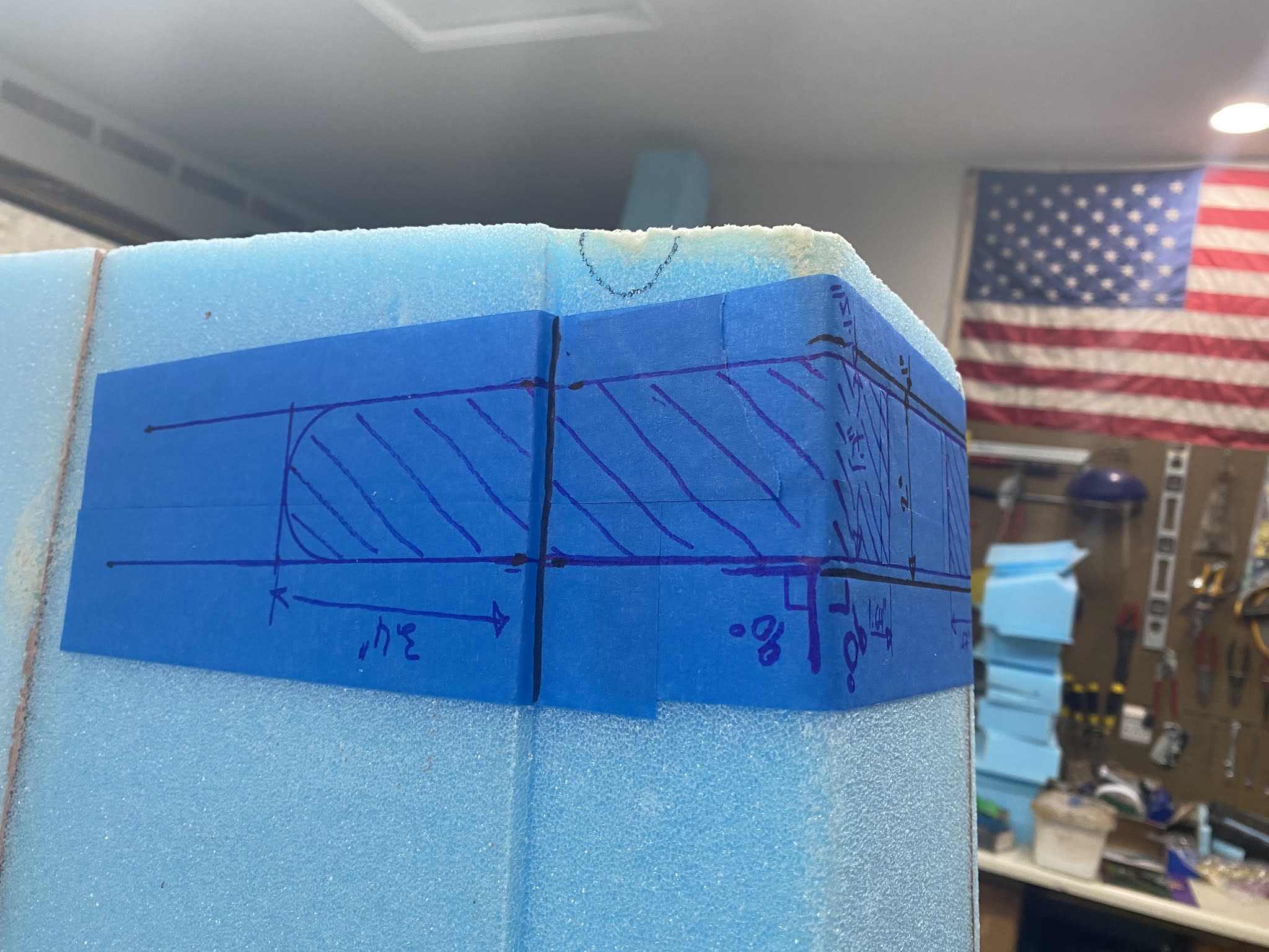
| Drawing dimensions on foam is difficult. I learned this trick from Walter Grantz (R.I.P. my dear friend). |
 |
| It's just regular painter's tape, nothing fancy, but the pen marks are much more readable. |
 |
| Bottom slot dimensions marked |
 |
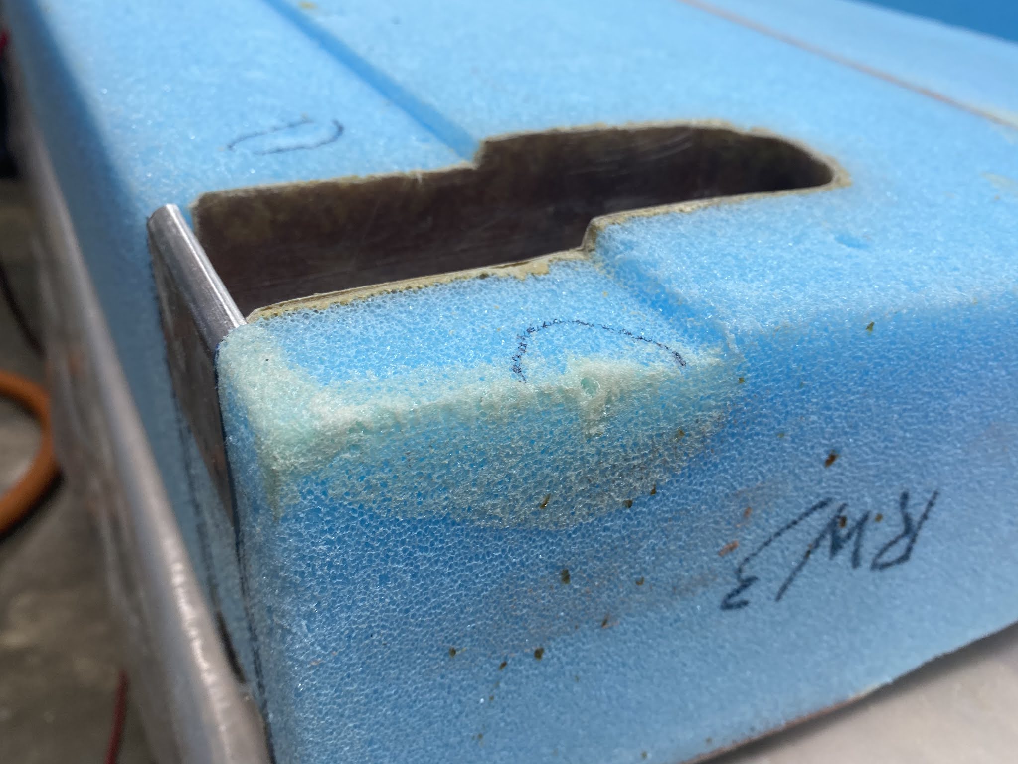
Establishing a reference plane (plexiglass) perpendicular to the front face of the foam
|
 |
| Using the reference plane as an aid to cut the slot to the charted depth |
 |
This was Ary's idea, and worked quite well.
|
 |
| The obligatory photograph for a future DAR (Designated Airworthiness Representative) |
 |
| Slow progress precision foam removal |
 |
| Here's a perfect variable depth slot perpendicular to the foam face |
 |
| Shimming the square to establish the reference plane on the opposite side |
 |
| Bottom slot cut using the same technique |
Wow, that was a little bit weird, but worked quite well. Time to glass the pockets.
 |
| I think I use as much duct tape as I do fiberglass building this plane |
 |
| Two plies of BID cut at 45º bias |
 |
| Foam slurried, and micro fillet applied to the edges. |
 |
| BID prepregged |
 |
| BID applied and peel-plied |
 |
| Always use a bigger piece of glass than needed, then trim later. |
 |
| What a difference a day makes! |
 |
| Slot trimmed and lightly sanded to remove all peel-ply strands |
Most of you probably already know what’s going on here, but for those new to fiberglassing let’s look at this process again in detail on the bottom side of the wing.
 |
| FC1 flipped over to repeat the process on the bottom slot |
 |
| One can never have too much duct tape |
 |
| Wetting the BID cloth with pure epoxy in between plastic sheets |
 |
| The result is what we call pre-preg |
 |
| Pre-preg means previously impregnated, referring to a ready-to-use epoxy soaked fiberglass sheet. |
 |
| Pre-preg is easier and less messy to work with. Just peel the backing plastic, and stick where needed. |
 |
| Then one works it down to the foam with an epoxy soaked brush |
 |
| Peel-ply added over the fiberglass (not required in this instance) |
 |
| The glass should have lapped slightly over the metal plates, but I chose to install them later. |
 |
| Peel-ply removal time |
 |
| Cleanup is alway a bit tedious |
 |
| Bottom slot ready for business |
I like the way those pockets came out. Now we just need to recess them, and the foam, so that we can fit the metal plates through which the wing bolts will connect to the main spar.
 |
| The two metal plates I should have mounted before glassing the slots |
 |
| Setting the Dremel tool to a depth equal to the thickness of the LWA4 |
 |
| Ready to remove material |
 |
| Foam and glass removed to accommodate the LWA4 plate |
 |
| Test fitting the bottom LWA4 |
 |
LWA4s need to be flush with the foam as they will be glassed over by the shear-web
|
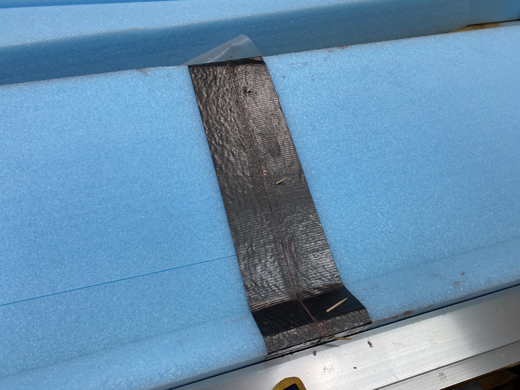
The plate didn’t line up exactly the way I would have liked, so I used toothpicks to hold it in place for the next step.
 |
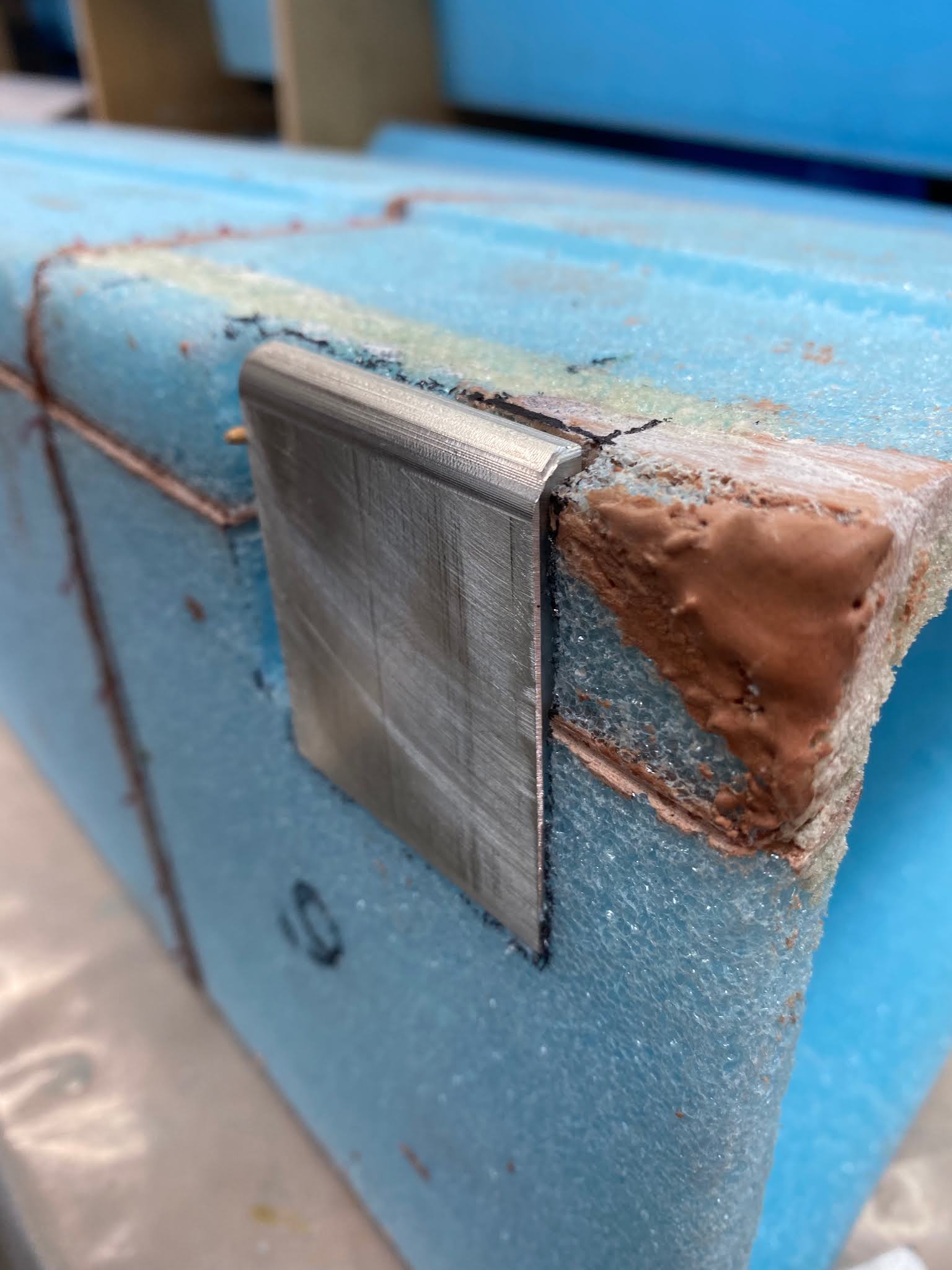
| Creating a flox corner by removing foam, and sanding the micro-slurry off the back of the glass. |
 |
| Using toothpicks to make up for my previous lack of control with the Dremel tool |
 |
| The toothpick trick worked amazingly well in lining up LWA4 precisely |
 |
| Flox in the corner (hence the flox-corner name) |
 |
| LWA4 and WI8 floxed to the slot |
In case you were wondering, I did not remove the toothpicks. There was really no need to do so, as the toothpick are stronger than the foam they displace anyway.
You might notice I used flox instead of micro here. I did this for two reasons. First, I wanted to create a flox corner between the fiberglass of the slot, and the fiberglass of the shear-web that will go over it (and the metal plates). Second, since I didn't lap the fiberglass slightly up the metal plate in the pocket (as seen in section B-B on page 19-12), a little extra strength there made me feel better. Probably not necessary, but definitely didn’t hurt anything.
The toothpick trick worked well by the way, and the plates lined up with the foam surface correctly.
 |
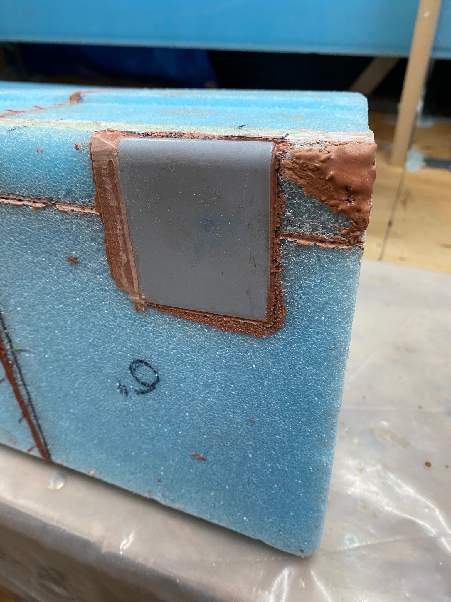
| The next day I double-checked for alignment with the foam |
 |
| The toothpicks certainly worked their magic |
 |
| Getting three surfaces to align at the same time can be a challenge |
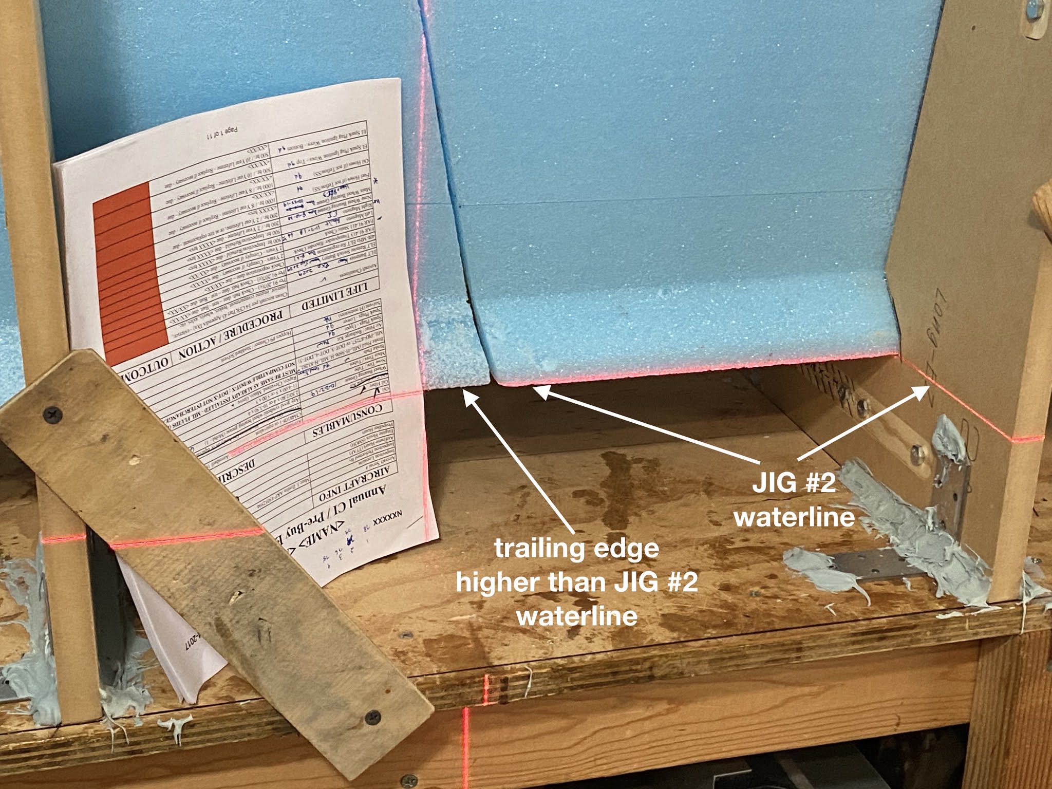
This might be a good point to bring up a Builder Hint from CP38…
 |
| JT doesn't have this, and I haven't had any issues to date, but #2 will get this soon. |
I’ll put that off until later. For now let’s concentrate on the top pocket using the same toothpick trick to line the metal plates up with the foam.
 |
| More targeted toothpick action |
 |
| Flox will close the slight gap |
 |
| Taped the two plates together |
 |
| Test fitting the plates together |
 |
| Duct tape means we are ready for business |
 |
| Floxing the corner |
 |
| Adding the metal plates |
 |
| Using some small tools to add weight to WI8 while curing |
Last but not least is the inboard wing mount.
 |
| Test fitting LWA6 |
 |
Duct tape to the rescue!
|
 |
| One last check after priming |
I used micro here since it will mostly be removed while glassing the wing root pocket at a later date.
 |
| Micro used here |
 |
| LWA6 curing |
 |
| Next day. LWA6 is there to stay. |
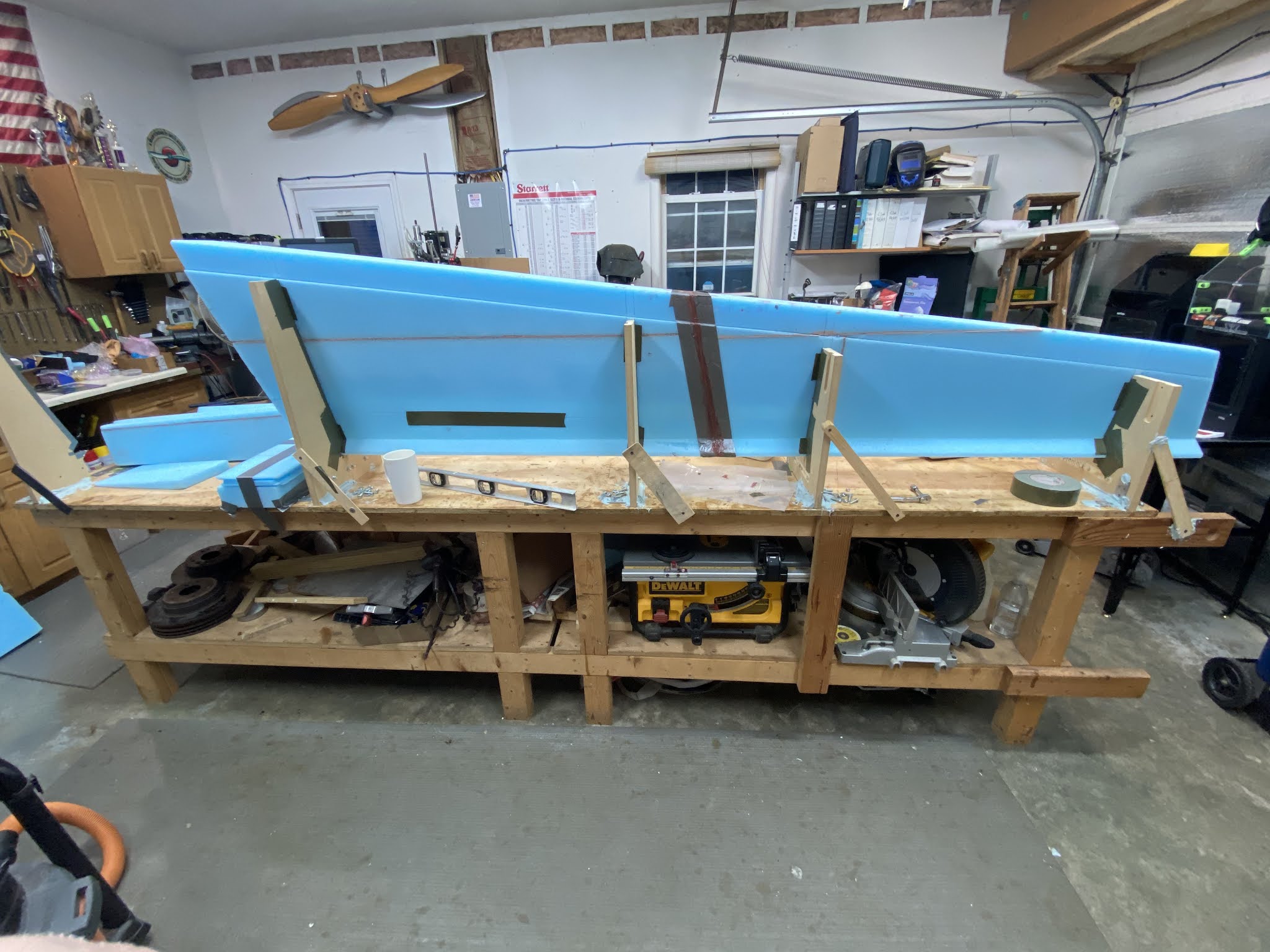
Nothing left to do but bond FC1 to the rest of the aft wing already in the jig.
 |
| Just as with the rest of the foam blocks, slurry and wet micro will glue them together. |
 |
| FC1 reunited with the rest of the aft wing in the jig |
 |
| The ever present duct tape |
 |
I used nails as usual to hold things steady while curing
|
 |
| One day later we are back in business, ready to begin work on the shear-web. |
Stay tuned, because next time we will begin the process of building the internal structural parts of the right wing.