Foam and jigs (22.8 hrs)
Perhaps it shouldn’t be, but this chapter has always been a little intimidating for me, not only are the wings the biggest single item of this project, but they also need to work… or else. You know what I mean?!
 |
Slightly foreboding, isn't it?
|
An issue that never previously crossed my mind has been the difficulty of maneuvering something so big and fragile around the shop. One soon runs out of space when working with so many wing pieces, and it always seems that anytime the foam is handled, more and more dents get added to the tally. So, reducing the number of interactions with the foam to those strictly necessary to the building process quickly became an imperative.
First things first though, time to get all the pieces of foam out of the many boxes they came in from Eureka CNC years ago, and put them together on the big table.
 |
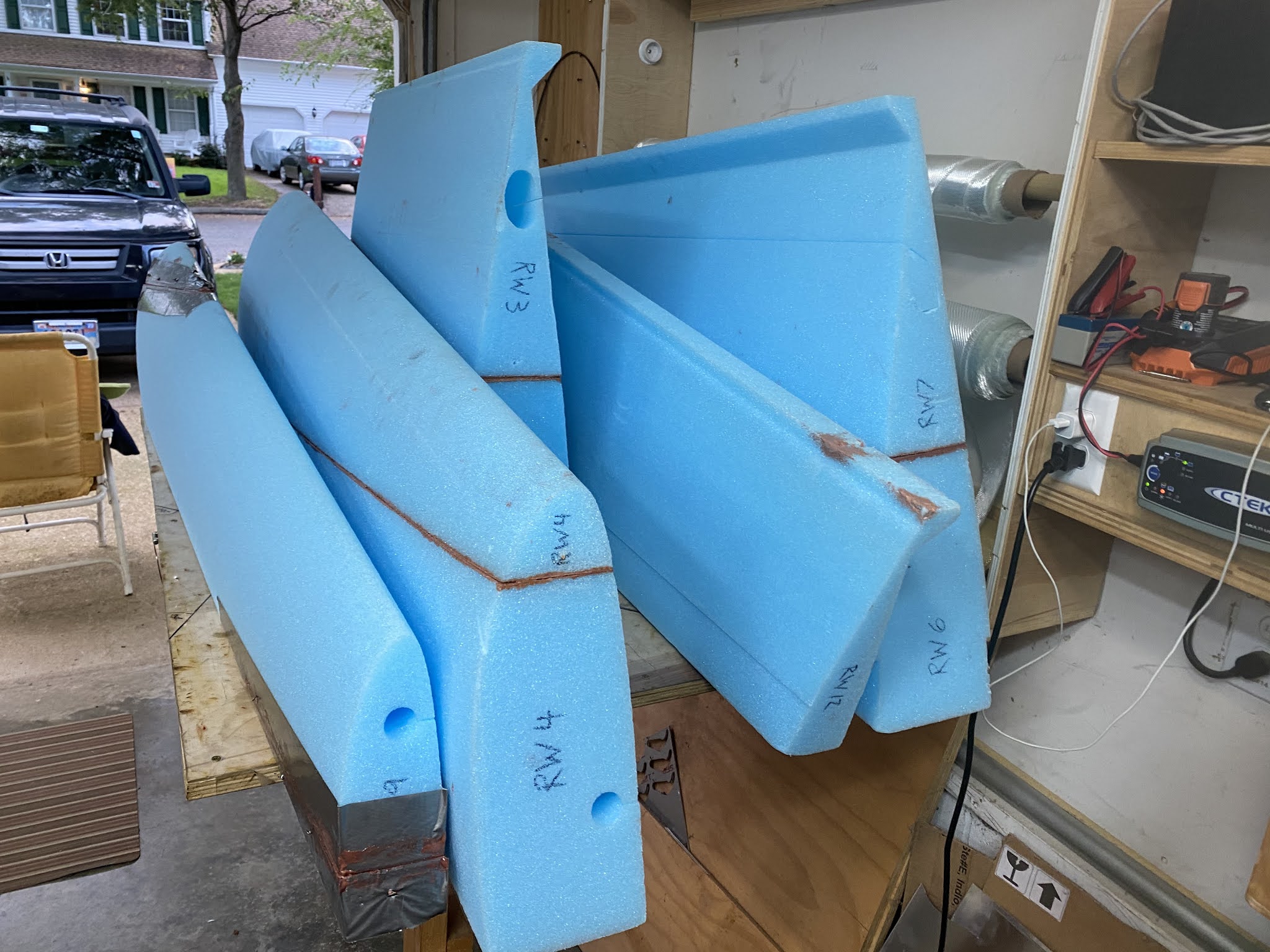
| RW (Right Wing) foam pieces emerging from long term storage |
OMG! This thing is humongous!
 |
| "What was that saying about how to eat an elephant?" |
 |
| "Oh yeah... one piece at a time... gulp!" |
The Long EZ plans only deal with five big pieces of foam, FC1 through FC5, but Eureka CNC cut the foam in thirteen pieces to make them easier and cheaper to ship, so it’s up to the builder to reduce these back to the five parts the plans describe.
 |
| Eureka CNC foam breakdown (plans' FC sections highlighted) |
And reducing I did… for three days.
 |
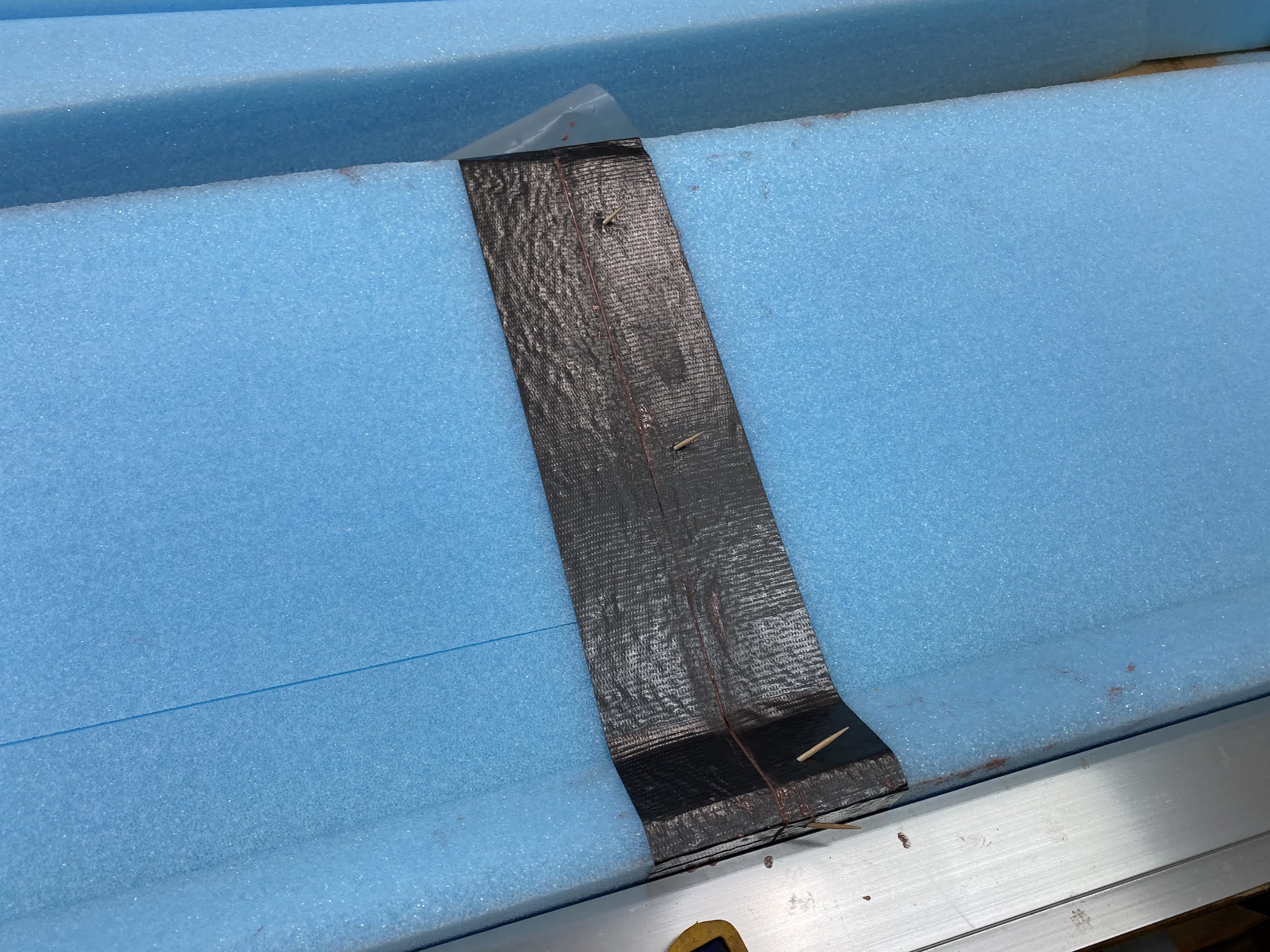
| As usual, tape and slurry the joints. |
 |
| Tried non-reusable toothpicks instead of nails this time |
 |
| Honda Element rear disk brakes are very helpful during this process |
 |
| Obligatory shot for future FAA observers, in case there is any doubt about who built this plane. |
 |
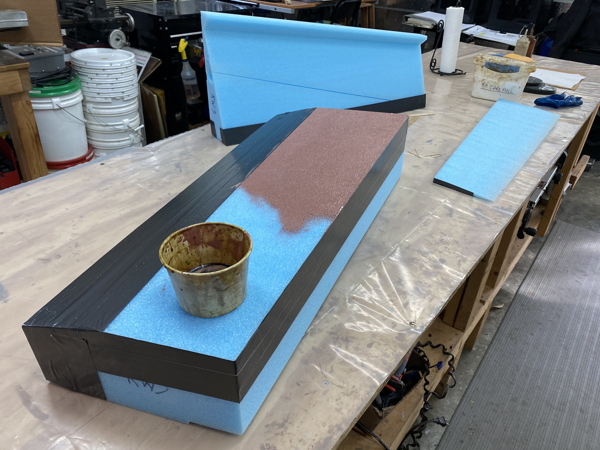
| It's amazing how fast big surfaces gobble cups of micro-slurry |
 |
| "Braking action report... Good!" |
 |
| Rounded pieces are a bit trickier to weigh down |
 |
| Using the same foam they were cut from helps immensely |
 |
| The weighing down process becomes even more complicated |
 |
| Using every trickery at my disposal to get the job done |
 |
| Creativity and resourcefulness are very much part of the job description when building a Long EZ |
 |
| Micro-slurry to close the foam pores, and wet-micro as a bonding agent. |
 |
| Had to use an extendable broom stick to reach both sides |
 |
| Foam puzzle to weigh down the leading edge on one end... |
 |
| ... and a rear wedge piece on the other end, at the same time. |
Admittedly I don't like to rush, and eventually I ended up with the five big foam pieces.
 |
| Wing pieces FC1 through FC5 ready for action |
With all the foam blocks accounted for, and the help of my trusty laser, I set out to build the straightest wing jig I was capable of, little did I know it wouldn’t turn out to be that easy. Even though my twelve foot table is super flat, leveled in every which direction, and I would be using Eureka CNC cutouts, issues would crop up.
My first step was establishing a straight line 125.6” (3.2m) long that would represent the forward edge of the wing cutouts. Now, I don’t have a straight edge that long, and the sides of the plywood top that make the table were never square to begin with, so I turned on the laser and traced the red beam on the table.
 |
| Tracing the red laser line on the table |
 |
| Dimensions are very specific on the plans |
The plans specify the locations along this line for the wing cutouts, which are also marked with a common waterline allowing them to be lined up vertically.
 |
| A flat and level table is a God sent in a situation like this |
 |
| All waterlines lined up on their own, thanks to the work we did on the table |
 |
| Still no shimming required at this point |
 |
| Four out of four here... scored! |
 |
| This is what I look at when I align the cutouts vertically |
 |
| Last cutout ended up needing a little help... Oh well! |
I didn’t have to shim any of them until I got to the very last one.
 |
| Used hotel key cards to shim the cutout up. I reckon 4 out of 5 is still pretty good. |
At this point I tried inserting the foam pieces into the cutouts, only to find out that that didn’t work, further damaging the foam. I ended up needing to disassemble all the cutouts in order to insert the foam, but I had already Bondo’ed the aft pieces in place, so I had to chisel that off. Note to self: don't repeat this mistake on the other wing.
 |
| Did not like having to do this |
 |
| Had to chisel off all the back pieces |
With that, the wing went in.
 |
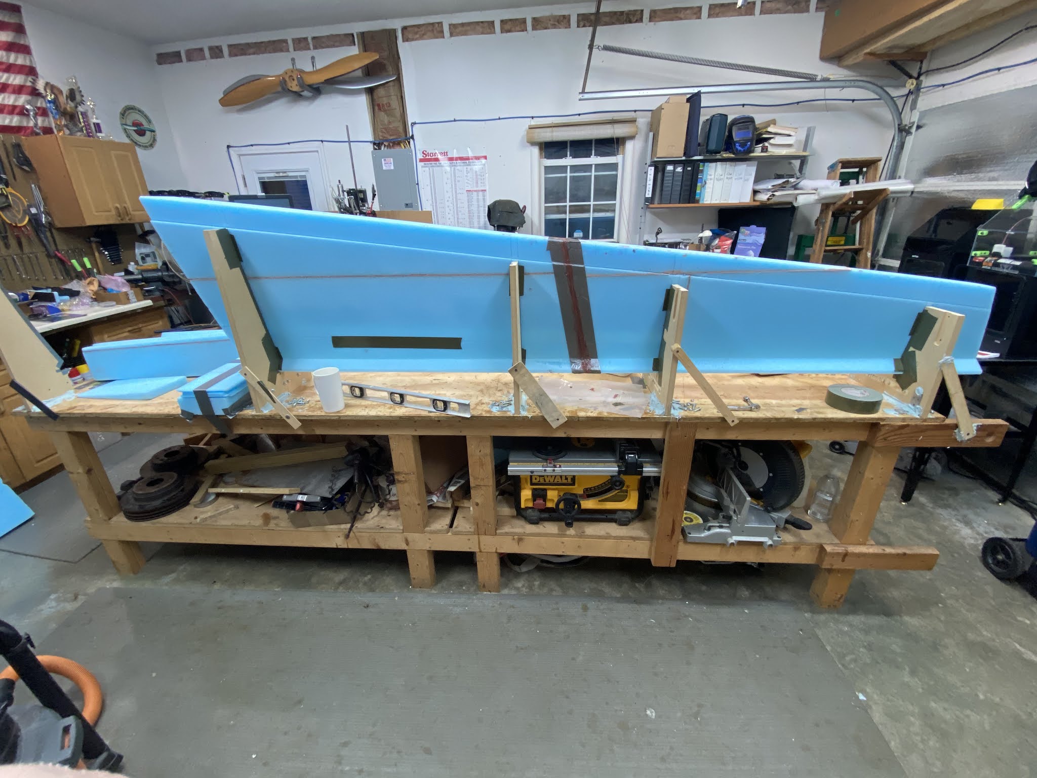
| Finally an operational jig |
 |
| Crap! This thing looks even bigger now. |
After a few minutes of contemplating what had I gotten myself into, I started noticing a few issues.
 |
| "What's happening here!?" |
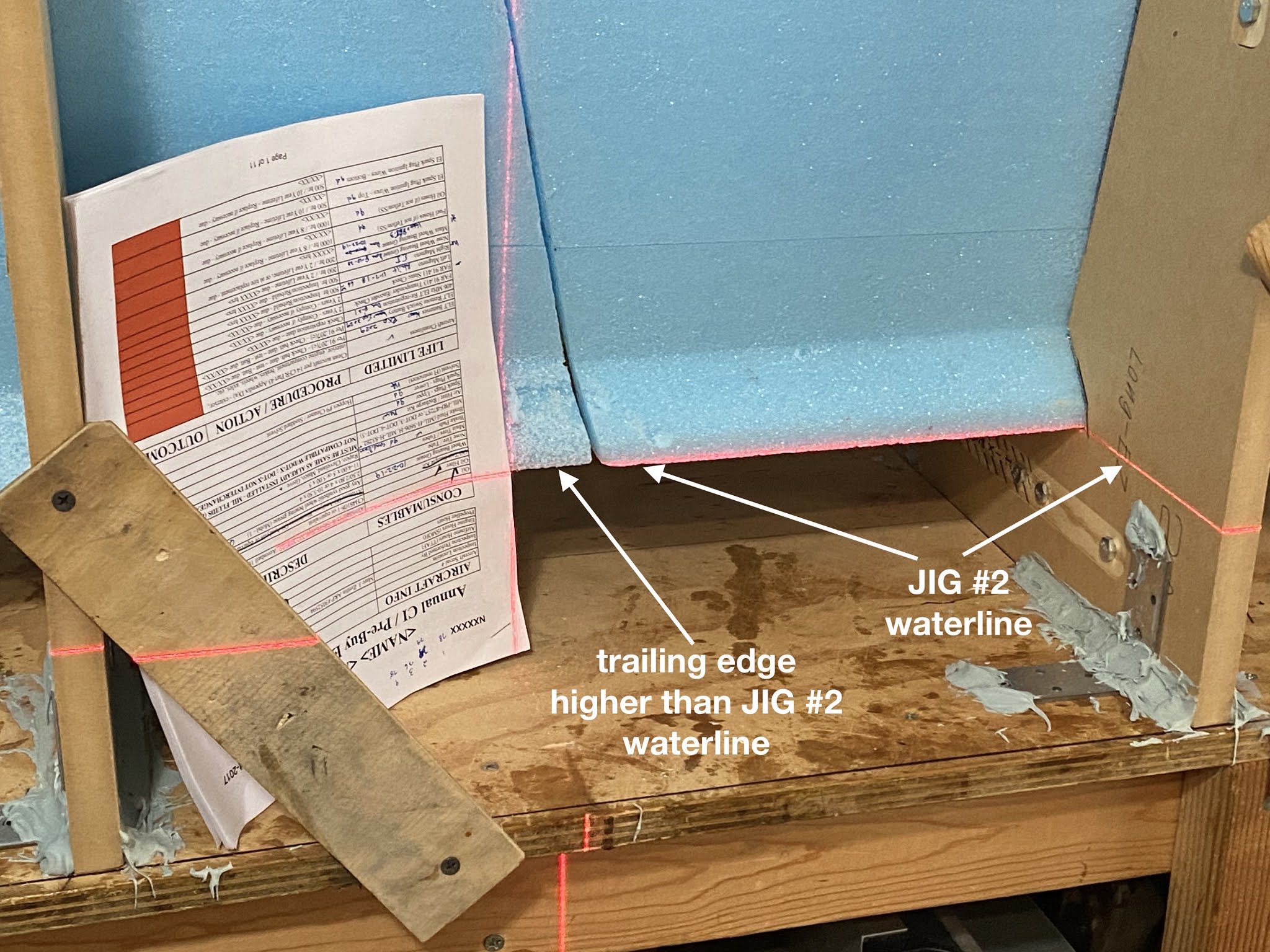
The more I looked at it, the more it looked like cutout #2 (second from the right) was too low, and that if I shimmed it up everything might fall back into place.
 |
| Measure with a laser and cut with an axe type of thing. |
Now, I had to make an executive decision. I could either keep my “straight jig” and build a crooked wing, or adjust jig #2 and end up with a straight wing.
Duh!
Shimming jig #2 up brought the trailing edges back in line…
 |
| Cutout #2 waterline offset up |
 |
| Now that's more like it! |
… and the spar-cap trough…
 |
| Much better |
… and the leading edge…
 |
| Checkmate! |
Yeah… I’ll keep that!
 |
| Marked the new waterline for when I build the left wing |
In addition to raising jig #2, it had to be pushed back about ⅛" (3mm) from the black reference line in order for the wing surfaces to match without a step.
 |
| Jig#2 backed off the reference line |
This will be a problem again later on when both wing and jig are flipped 90º on that side.
Meanwhile, let’s bond the two bottom pieces before they move again.
 |
| FC2 and FC3 taped before bonding |
 |
| A high level view of the job at hand |
 |
| Foam bonded the same way as previously done with the smaller pieces |
 |
| Used removable nails to prevent the foam from shifting overnight |
 |
| Bonded the foam to the jig, top surface only, per plans. |
 |
| Cleanup the next day |
Next time we will be creating the wing root pocket on the first foam block (FC1), and begin installing the wing bolts mounting plates.
 |
| JT's right wing root pocket |


No comments:
Post a Comment