Chronicling my Long EZ construction (and a few other things).
Disclaimer
This blog is for entertainment purposes only, and is not meant to teach you how to build anything. The author is not responsible for any accident, injury, or loss that occurs as a result of reading this blog. Read this blog at your own risk.
The nose gear leg (NG-1L) is a fiberglass piece I bought from FeatherLite last year together with the main gear bow.
Main and nose gear legs
While the main gear needed a lot of BID reinforcement to add torsional rigidity, the nose leg only takes 2 layers of BID for... as the manual calls it... “split protection”.
Plan's directions
First as always, I knocked the slippery shine off the nose leg with the sander, being careful not to remove too much material.
Sanding, the EZ way.
To quickly remove the corner sharp edges, I secured (in a very unsafe manner) my router to the big table, and ran the leg past the router bit as if it were a router table.
Routing the corners
I still had a bit of manual sanding to do, but it was easily done with my perma-grit tools. Speaking of which, I’m finding myself using the flat one more than any other of them, followed by the round tube sanding tool.
Glassing was the usual sequence of cutting the glass, wetting the piece with pure epoxy, applying the glass and epoxy, and peel-plying where needed.
BID selection
Pure epoxy sponge bath
BID pre-preg application
Peel-ply added
After cure, I removed the peel-ply, flipped the part over, and Bondoed it to a couple of screws, exactly as I did when glassing the main gear, to make a sturdier setup, then repeated the glassing procedure.
Front of the leg about to get fiberglassed
Sleeping beauty curing overnight
The Saran-Wrap helped hold down the edges, and prevented air from being sucked into the layup from above.
Another overnight cure, a little trimming, and voilà... a ready to use nose gear leg.
Quick way to get rid of the sharp edges
NG-1L done
The biggest source of concern at this point was to make sure the 4 holes attaching the leg to the NG-6A casting were drilled so that the far end of the leg would be centered between both NG-30s. I used shims and a caliper to arrive at equal gaps on either sides of the leg.
Finding the center position
Desired position captured by the clamp
NG-6A and NG-5. The top of the nose gear leg needs to go in there.
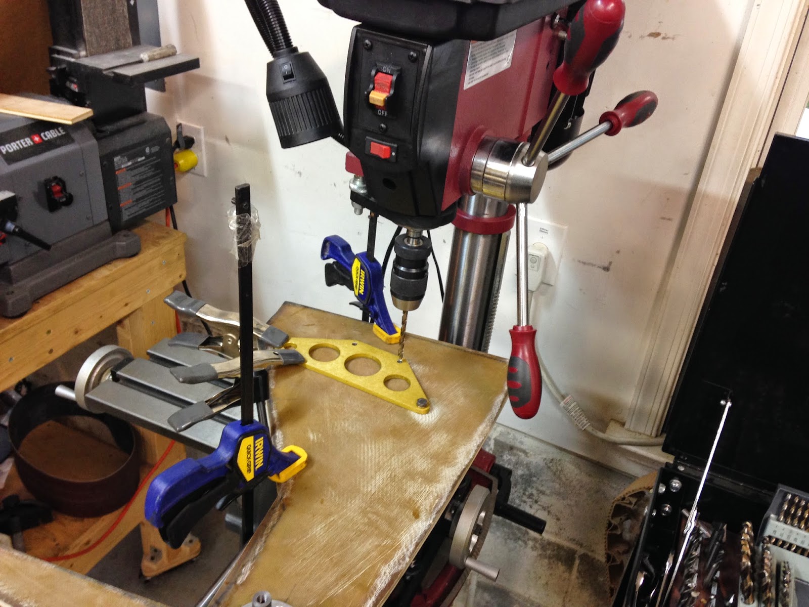
With NG-6A clamped into the desired position onto NG-1L, I transferred both of them to my drill press. Since the nose gear is bowed, I used parallels to make sure that the casting’s reference machined surfaces were parallel to the table before drilling.
Parallels (one on each side) ensure the casting is horizontal
For the actual drilling operation, I switched to a more rigid way of holding on to the work.
Nothing should move now
Holes were drilled as far as possible (half way), then finished by hand on the bench.
The holes drilled in the leg matched the ones on the casting (NG-6A) as well as the ones on the top plate I made on the mill (NG-5), and everything fit as I expected, until I tried to bolt it all down.
This just isn't going to work!
Another day in the life of a non-kit builder
The other side is good
As if I needed another reminder that I was not building one of those exquisite Van’s RV kits, a fair amount of custom grinding with a Dremel wheel proved necessary to make sure all washers laid down flat enough to bolt it all together.
Today’s addition to the CNC mill conversion project belongs both in the “cool things to have”, and the “absolutely not necessary” categories.
Walking around the shop carrying a wireless keyboard had gotten a little old, so I knew I wanted a dedicated remote controller for the mini-mill. I was prepared to spend around $100 on one, but then I saw a guy on YouTube who used an xbox controller on his CNC router table.
A quick check on eBay for genuine Microsoft xbox controller (important detail) revealed that one could be had for around $25, so I decided to give it a try.
The file and instructions on how to hook it up and run it can be found here(toward the bottom of the page).
running the mill with an xbox controller
The wireless version of the controller is supposed towork with Mach3 as well, but I hear that most other non-Microsoft controllers run into compatibility issue (read: random nasty mill crashes), so be careful what you get into.
With the mill mostly completed, the time has come to enlist its services in the production of the first few airplane parts, and since I’ve still got a lot of learning left to do, I tried stacking the odds in my favor by selecting two easy part to make, at least in theory.
NG-8 and NG-5 are mostly a 2D cutting job. There are a few holes, profiles, and some chamfering to top them off.
What could go wrong?
I’ll concentrate here on NG-8, since NG-5 benefitted of all the lessons I learned in producing the former.
What I was trying to achieve
But first, the two flat panel (NG-30) that make up the nose structure needed to be drilled and sanded together to ensure they’d line up later on. That's what the NG-8s will attach to.
Matched drilling the 2 nose frames
Cleaning up NG-30s while mated
Getting back to the story... NG-8’s are aluminum round plates (2 needed) that flank the nose gear hinge mechanism (NG-6A), and bolt on the NG-30s.
NG-8 plans' description
NG-6A nose leg hinge casting
Left and right nose frame structures (NG-30)
I cut two aluminum blanks on the band saw, and went to work.
NG-8s in the making
The way things really went!
The engraving was a bit of an overkill since it won’t be visible from the outside, but what the hell, I think they look cool anyway.
Long EZ jewelry
It's hard to photograph something that shiny
Obviously, I could have knocked both NG-8s out in about an hour, had I done it by hand, instead of the 2 weeks I spent working on them. But that’s not the point. I learned a lot from making them, and NG-5 took just 2 hours, and produced no scrap pieces. Still a bit long, but exponentially shorter.
The lesson on fixtures was also not lost on me, and that’s the first thing I made (on the back side of the NG-8 one) when I made NG-5.
NG-5 fixture
Perfect countersinking on NG-5
Test fitting NG-5 to NG-6A
Next, I mounted the NG-8s on the nose frame.
Marking the hole locations
Drilling the 4 NG-8 holes
Screw inserted to prevent NG-8 rotation
Outer NG-30 pivot point hardware
Same thing on the inside
NG-8s might never be seen again
I still had the holes on the actuator brackets to transfer onto NG-30s, so I started drilling on right one.
Transferring the bracket holes to the nose frame
Later, I mated it with the left one and went through all holes once again with the drill press.
NG-30s bolted together for further drilling. Motor depressions on the top are now evident.
Same thing, different angle.
Drilling the top bracket holes through to the bottom NG-30
Last to get drilled were the clearance holes at the very top (1”, 2.5 cm), for the actuator hinge bolts.
The biggest drill bit I own
All the holes are now drilled. The dark areas mark 34 layers of BID, and one of Kevlar.
All there was left to do was to bolt them all together, and see how they all fit.
Nose structure completed
Left view of the nose structure
The depressions in the foam to clear the motor gearbox worked out perfectly
I was never comfortable with the way the Z axis ball-screw attached to the head of the mill. The main reason for this was my inability to mark the exact location of the bolt holes with the accuracy they deserved.
I wanted to be able to compensate for the slight positioning errors I was sure to make while determining where to drill in the cramped quarters of the mill’s head.
To this effect the plans I purchased were of no help, since they merely showed a plate with holes in all the right places, and left you to find out where those would be on the mill.
Original plans provide no adjustability
I spent quite some time mulling this over, then decided to do it my own way. My design would allow for X and Y adjustability of the ball-screw plate attachment points, or so I hoped.
Bottom plate adjusts in Y direction, and connects to the mill's head.
Top plate adjusts in X direction, and connects to the ball-screw.
In between fiberglass curing cycles, I started work on my new plates design.
Milling the slots (with 2D CNC of course)
Top and bottom plates finished
Checking fit on bottom plate slots
Bottom bolts are covered up by the top plate (not so good).
Testing the adjustable design in X
I also took my most precise estimates of where I should drill the bolt holes, in order to increase the adjustability potential.
Best estimate for the 3 bolt holes
Disassembling the head of the mill is not something you want to do very often, especially now with all that CNC jazz on top of it, but I had already been putting this task off for as long as I could have, and now it was finally time.
The head could just barely fit in my 6" (15 cm) vise on the drill press, and I set everything up very carefully.
Aligning everything up
I was just about ready to drill, when I finally realized there was a big problem.
You see, the mill’s head is made of 2 pieces bolted together with 4 big bolts, and they were going to be in the way of the ones I was planning on installing.
The big bolts are hidden when the head is installed, and I forgot these suckers were even there, but they didn’t, and couldn’t pass an opportunity to bite me in the ass as soon as I turned around.
Can you see the problem?
Crap! Back to the drawing board.
After more head scratching, I decided to swap bolt locations between the bottom plate and the top plate. This new setup would clear the “danger below the surface”, and would allow me to make the top plate even smaller, with the added benefit of uncovering the head of the lower bolts, making them adjustable without having to remove the top plate.
Bingo!
New and improved bottom plate
Smaller top plate (looks like a square Napster)
Smaller top plate does't cover the bottom bolts anymore
Z axis lower assembly
Machining resumed on two new aluminum pieces.
Using CNC you can cut any size hole with any size mill (as long as it fits in the hole), check it out...
Cutting the hole on top of the top plate
I guess I also won't be using my counterboring set very much anymore...
Counterboring the hole on the bottom of the top plate
Cutting the same slot on both plates
With the head of the mill back in place, I was able to find some new bolt hole locations. Oddly a small shim was needed. I might end up trimming the bottom plate later on, and getting rid of the shim.
Assembly in position, looking for new bolt hole locations.
Note the small shim?
The holes were at last drilled and tapped, and the whole thing put back together for final testing.
Tapping new holes on the drill press
Bottom plate in the fully aft Y position
Bottom plate in the fully forward Y position
Assembly bolted to the mill's head at last
Testing the newly bolted together Z axis
"Air cutting" a 2" wide slot, down to .100" depth, in 4 passes.
That’s it folks, the CNC mill is done! It has taken excactly 1 year from start to finish.
There are a few small things left to do, like spindle control, limit switches, etc., but I’m calling those... improvements.
The CNC mill is here right now, it can do some real work, and I might just have a couple of things in mind to get me started making chips.