Disclaimer

This blog is for entertainment purposes only, and is not meant to teach you how to build anything. The author is not responsible for any accident, injury, or loss that occurs as a result of reading this blog. Read this blog at your own risk.

Tuesday, June 19, 2012

Ch. 5 - Fuselage sides - Part 1


Foam board magic (5.0 hrs)
I have finally arrived at the first substantial part of the construction, and part of the reason why I built the “monster-table”.
The fuselage sides are way too big to be made out of one single piece of 3/4” thick foam, so I will have to glue at least 3 pieces together, and cut as necessary.


Blue foam and wood longerons


The upper part of this drawing shows the blue foam already cut to dimension, while the bottom shows the assemblage of foam, and wood longerons, and the location of the bulkheads.
Because the top longeron will become a very important reference point later on, it is necessary that the foam that attaches to it, be as straight as possible to begin with. I used a straight edge to line up the foam boards while I glued them.


Making sure this edge is straight


Once again, I used some duct tape in the back of the seam, so that I could spread the joint apart without losing the careful alignment.


Next, I whipped up a new batch of wet-micro. 


Wet-micro


The reason it looks so white, is that I used leftover West epoxy instead of the usual E-Z Poxy. This is not a structural connection, so I elected to go with the fast curing stuff, in order to get this project back on the road.
Anyways, like I was saying, I whipped up some wet-micro, and filled the joint with it.


After unfolding the foam boards, I cleaned up the excess.


Then, I used every heavy item I could find, and weighted down the boards to allow them to dry as flat as possible.


Using every heavy object in sight to keep the foam down


Later, I flipped the foam boards over and ripped the duct tape off.


Taking off the band-aid


Needing more foam to reach the 103” dimension, I cut the width in excess of 21”.


Excess foam trimmed off


Then cut a piece off of that, and glued it in the back of what is now a really big foam piece.


While waiting for the wet-micro to set, I decided to start cutting the wood for the longerons, stiffeners, and gear mount build-up area. 
Oddly enough, while laying out the drawing on the wood, I kept coming up with some misalignments in LWX. 
So, I decided to verify the angles on the plan’s drawings, and I noticed that one of the angles is incorrect. It was probably just rounded down to 35˚ for simplicity, but the correct angle should have been 37.5˚.


atan(1.0/1.3) = 37.57˚


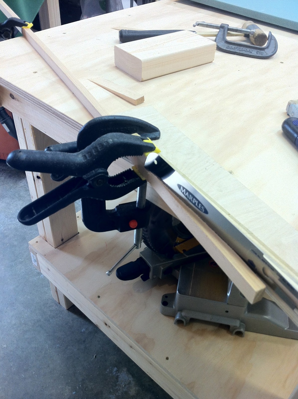
Setting up a cut like that on the miter saw is impossible, because one would have to cut the complementary angle 52.5˚, while the saw only reaches 50˚. To get around this limitation, I cut a 2.5˚ slope in a piece of scrap 2” x 4”, and used it to back up the part I was trying to cut. 
With the miter saw set at its maximum 50˚, and the 2.5˚ slope cut into the scrap wood, I was finally able to line up my blade with the target cut-line, and easily produce a 37.5˚ angle.


Note the shadow of the blade lined up with the cut line! :-)


The opposite end of LWX, as well as LWY, were easy 45˚ cuts. 


Producing the 103.5” longerons was as easy as measuring, and cutting. The stiffeners though were a bit more involved. First, I had to rip a 1” piece into two 0.4”.


Ripping him a "new one"!

Two "ones", perhaps?


Then, I had to shape them at an odd 4.6˚ by hand.

Are all these weird cuts really necessary Mr. Rutan?

This thing could put an eye out!


So, this is as far as I’ve gotten today.


This is as close to a "Long EZ kit" as it gets.


In the next session, I will shape the fuselage side I made today, and try to glue, and shape another one as well.


UPDATE

I should have left LWY a couple of inches longer because I ended up having to extend it later. 

I have heard from a few builder friends that they ran into the same issue as well, so I'd suggest leaving it long and trim it at a much later date.


Thursday, June 14, 2012

Shop preparation - Part 4


The BIG worktable
I have been on the road for the past two weeks, and haven’t been able to get much done. 
The one thing that I have been able to work on while I was away, is the design of the 11' x 3’ (3.3m x 0.9m) table on which I will be building the fuselage sides, canard, and wings.
I wanted this table to be built in such a way that I could later cut it with a circular saw, and split it into two identical 5.5’ x 3’ halves that I'll be able to reuse in the hangar (don't have one yet).
Because the previous table I made, loosely based on the “standard EAA table”, turned out to be such a sturdy, and simple piece to build, I decided to enlist the same design once again. This time I planned for additional modifications to suit my specific needs, like a 1.5" overhang around the perimeter, to facilitate clamping things, and a lowered bottom shelf, to allow for the storage of bigger items.

Table frame designed with iPad CAD App for carpentry named Woodcraft.

For those who would like to replicate my table, I'll insert a few info here.
The material needed for the table consist in twelve 2" x 4" x 12', and four 4' x 8' sheet of plywood (the thicker the better, I suppose), mine were 0.75" thick.  

Twelve 12-footers going home. 

From this I cut the following:
- two 2" x 4" x 11' (top beams)
- two 2" x 4" x 10' 9" (bottom beams)
- twenty 2" x 4" x 30" (cross-members)
- eight 2" x 4" x 8" (leg parts)
- eight 2" x 4" x 18" (leg parts)
- eight 2" x 4" x 33" (leg parts)
- two 3' x 5' 6" (table top)
- two 2'9" x 5' 4.5" (table bottom)

2" x 4" ready to be assembled.

Unfortunately the Home Depot lumber guy cut my table bottoms 1/2" too short, so I do not have the contiguous bottom shelf I was going for, but one with a 1" gap in it instead. No big deal, but be careful when you get yours cut.

To achieve consistent results when cutting many equal parts, like the legs or the cross-members, it is helpful to set up a simple jig to be used with the miter saw. Mine consisted of a block of wood clamped to the bench, at the desired distance from the miter saw's blade. It made cutting the 12-footers fast and easy, and the little time spent setting it up paid off later, when everything fit together precisely.  
When the time came to put the legs together, I made another simple jig that allowed me to quickly stack and line up the 2" x 4". Additionally, instead of measuring the space to leave for the top and bottom beams, I used a couple of scrap pieces as spacers.  


Assembling one of the legs.


This worked so well that, at assembly time, the table was so tight it was holding itself up without screws.  

Top and bottom pieces hold the table together without screws (screws added later).

I used 2.5" #10 screws for the legs, and 3" #10 screws for the cross-members. Top and bottom plywood used 1.5" #8 screws. I did pre-drill all of the holes to avoid wood splitting. 
To make sure the top and bottom surfaces would come out as flat as possible, I built the  top and bottom frames upside down on the floor.

In the end, this turned out to be a pretty simple one day project, that anyone with basic skills and tools could tackle. The quality of the table is very good for garage standards, and it is very sturdy. You might consider equipping it with wheels, if space is at a premium, but in my case I plan on leveling it, and not moving it again until I'm finished with it.


A floating 2" x 4" (below plywood top) ensures a smooth transition 


Tuesday, May 29, 2012

Ch. 5 - Landing Gear mounts - Part 5


More sanding, more drilling (7.5 hrs)
The small landing gear brackets (front) have to go through the same process as the big ones (rear) did. Basically, drill the mounting holes undersize, ream them to the proper diameter, mill the lightening holes, and sand it all to shape.
The paper templates proved themselves to be quite precise, and the holes I have drilled so far have ended up with the correct placement.

Front-right landing gear bracket lined up behind rear bracket .


Front-left landing gear bracket lined up behind rear bracket.

In spite of this, I decided to use the templates just for initial positioning, and employ the actual brackets for proper alignment of the holes instead. This way any error in the rear brackets would get duplicated onto the front one, guaranteeing parallelism between the LMGA tubes, and the fuselage sides.
I used the table to make sure the brackets lied onto the same plane, and once the hole and the template lined up, I clamped them together.

Immobilizing brackets before drilling.

I then mounted them on the mill vise, and spent some time leveling them precisely, so that the holes would turn out perpendicular to the surface.

Leveling brackets with the help of a dial gauge.


I used the 1/4” reamer fitted to the mill head, to line up with the hole in the rear bracket (the one on top). Then I removed the reamer, and the rear bracket, and used a series of increasing drill bits to bring the hole to 7/32” (5.55 mm). Finally, I enlarged the hole with the 1/4” (6.25 mm) reamer.

Reamer lined up and ready to roll.

If you have never used a reamer before, here’s a short clip of myself reaming one bolt hole. As you’ll see, it’s pretty similar to drilling a hole, except that you need a hole already made to begin with, and you do not want to run the bit in reverse or you’ll risk damaging it. These reamers are pretty delicate tools.


I used this same technique for all the mounting holes, as well as for the lightening cutout.

Aligning 3/4" end mill.

Here’s a video of the milling of the lightening hole. I decided to add it because it’s pretty wild, with lot metal chips twirling about, but it’s also 4 minutes long, so watch it if you’re into that kind of stuff.


Later, I bolted the two front brackets together, and sanded them to shape. Here they are after sanding. 

Completed left and right front brackets.

Finally, I was able to put all of the pieces that will attach to the rear, inner fuselage skin, together to form the main landing gear attachment points. Here are a few pictures of the finished product. 

Complete right assembly.


I used some bolts to join them loosely, to see if the holes would line up. Given all the variables involved, and the cumulative small errors, it’s kind of scary how precisely they mirrored each other.


Tuesday, May 15, 2012

Ch. 5 - Landing Gear mounts - Part 4


Sanding brackets and drilling holes (8.8 hrs)
I had already roughly cut the landing gear brackets, so today I sanded the big ones  smooth, and drilled all the holes required in the plans. I spent some time leveling the bracket in the vise, to make sure the holes would be drilled perpendicularly.
I made all the holes 1/32” (0.794 mm) undersize on purpose, then used the appropriate size reamer to enlarge the holes to the correct diameter specified in the plans. This extra step is probably not necessary, but ensures that the holes are perfectly circular, and precisely dimensioned. 

About to enlarge gear mount main hole.

Reaming rudder cable pass-through hole.

After all of the mounting holes were completed, I moved on to the lightening holes. I did not have a 3/4” (19.05 mm) drill bit, but I did have two end mills in that size, one of which suitable for plunge milling.

Plunge/side cutting mill (left), and side cutting only mill (right). Note the different head profiles.


With it in the collet, I started cutting the holes in the first bracket as depicted in the paper template.

Removing weight, every ounce counts.


Before starting on the other bracket I bolted them together loosely, so I could sand them smooth, and to the same shape.

Evening things out.

Instead of relying on the paper template glued onto the second bracket, I aligned the uncut bracket with the previous one using bolts. I used this set up to position the cutting tool, thereby guaranteeing the symmetry of the pattern.

Lining up the end mill.

I am pretty satisfied with the way they turned out, see for yourself below.

Finished brackets.


Next to the plans.