Chronicling my Long EZ construction (and a few other things).
Disclaimer
This blog is for entertainment purposes only, and is not meant to teach you how to build anything. The author is not responsible for any accident, injury, or loss that occurs as a result of reading this blog. Read this blog at your own risk.
Thursday, February 09, 2023
Top overhaul
In
2016, five years into building my very own Long-EZ, I "accidentally" became JT’s latest proud owner.
Meeting JT for the first time
At the time it seemed like a good idea... Fly JT while building the other one, learn as much as possible and incorporate desirable changes to my own build, then resell JT after my project's first flight. So, after a what I thought was a thorough pre-buy inspection during which a couple of
issues were discovered and corrected, JT followed me home.
One
always buys a used airplane hoping not to run into too many issues,
nevertheless issues always seem to have a way of finding you.
Oh boy!
So in 2017,
after just one year of occasional flying, JT came down with a case of low compression in all cylinders that couldn’t be helped, no matter what we
tried. Interestingly enough, JT never showed any signs of slowing down,
but my A&P did not feel comfortable passing the annual Condition
Inspection anymore.
Saying that I was bummed would have been an
understatement. With roughly 800 hours on the engine, and a suggested
TBO (Time Between Overhauls) of 2000 hours, I was horrified at the
prospect of performing expensive invasive maintenance on my still new to
me airplane.
It turns out that not all engines make it to TBO, and statistically speaking the ones that do are engines that are used very often, like flight schools’
engines. Looking at JT’s logbook it appeared that she flew an average of
50 hours a year since she was finished in 2003. That was a
little disappointing, but in line with what most airplane owners
experience.
The verdict for JT was a “Top Overhaul”, and it would
not be cheap even doing most of the work myself under the supervision
of my trusted A&P.
If you haven't read this book you are doing IT wrong
These
books most definitely helped me understand what I was up against. I
cannot say enough good things about both, and I wouldn’t consider
working on an aircraft engine without the background information they
provided. They scared the crap out of me, and made me very cautious
about how performing even seemingly insignificant tasks incorrectly
could be disastrous.
I would also dare to say that Mike Bush’s
book should be mandatory reading material for all piston engine pilots,
as it relates strongly to how to operate one’s engine. Yes… it is that
good, and it is critical that you know what’s going on with your engine
if you want that relationship to last.
If you have ever worked on
a car or motorcycle I’d say this type of work is not any more difficult
than what you have already experienced, with a couple of differences…
1) certain “aviation only” tools are required, and 2) everything you
touch can potentially kill you.
About point #2, because of what I
learned from these books, I decided to not reuse any fasteners, and go
new on just about everything that needed to go back on the engine.
Cylinder flange bolt hole. Note the supercritical absence of paint. Why? Read the books!
Brand new hardware. These nuts are not symmetrical.
Case nuts are directional, but you wouldn't know it without reading the aforementioned books.
Because
cylinder removal is the only real opportunity one has to asses the
health of internal parts like the super important camshaft, I made sure to
have plenty of expert eyes on it, and luckily for me JT’s was in good
shape. The alternative would have meant a complete rebuild, something
that was definitely not in my 2017 budget.
As always good friends are better than gold, and I relied heavily on the advice of Jim Parkman (owner of KCPK’s Epix Aviation),
who helped me pick all the replacement parts I needed, and even trusted
me to borrow some of his valuable calibrated torque wrenches to
complete the most critical tasks. His advice and support are in large
part reason for the success of this maintenance evolution.
Fun fact, this wrench used to belong to my previous employer Atlantic Coast Airlines.
I splurged afterwards and bought an identical torque wrench to Jim's from the Snap-On dealer ($$$$)
As
for the cylinders I decided to go new, since the price difference was
not as high as the peace of mind I'd get from them, and chose Nickel
Carbide coated cylinders from ECI. Ironically, ECI was bought out by Continental
Motors, so all of my Lycoming cylinders bear the Continental
manufacturing logo.
New cylinder unboxing
The Continental logo made me pause for a second
Sleeping beauty
Pistons were already installed but had to come out for mounting
JT was originally equipped with a Lycoming O-320 E2A core and high compression pistons (160 hp),
so I chose not change anything here and went with high compression
pistons again made for the O-320 D2J version, so this did not change
JT’s power output.
Lots of additional new parts to go with the new cylinders
Taking the piston out of the cylinder
Temporarily installing the wrist pin
JT now (2018) runs a O-320 E2A engine core with D2J pistons, although four years later (2022) this engine will become a fully fuel injected unit (IO-320), but this is the topic for another post.
Baffles, intakes, exhausts, starter, and alternator removed.
Cylinders #3 and #1 from above
Cylinders #2 and #4 from above
Cylinders #2 and #4 from below with intakes and exhausts removed
Cylinder #1 with the valve cover removed
Using my middle finger to push out the rocker arm and bushing
Rocker arms, and pushrods removed.
Removing the 8 bolts holding the cylinder with one of two special wrenches
Making sure #1 steel connecting rod does not fall and dent the aluminum case
Repurposing the used cylinder's orange silicone O-ring to suspend the connecting rod
Pushing out the piston pin, and plugs.
Letting the connecting rod dent the case would create oil leaks on the reassembled engine
Special tools make the job go so much easier
Aside from the lead deposits on top, this piston still looks pretty good.
Rings are still able to move, a little scuffing on the skirt perhaps.
Carbon and lead deposit, and signs of mild scuffing near the edge.
Obviously not new, but not as bad as I was expecting it to be.
From
the look of things, these cylinders have been running hot for a very
long time, evidenced by the burned paint and pink coloration in a few
places. Unlike steel, aluminum slowly degrades with repeated heating cycles,
and overheating can quickly weaken the structure of the cylinder head,
and spell future disaster. This was one of the factors in my decision of going
all new.
Pink by the exhaust port (right) is a definite sign of overheating
Here's a better look at the exhaust port
An overall look at cylinder #1
Looks like some more pink around the spark plug hole
Dirk (my trusted A&P)
and I removed, examined, and replaced cylinder #1, after that I was on my
own, though he came back to double check my work a few times. We did
find a little scuffing by the pistons on a few cylinder walls, but never came up with a
real smoking gun for the lack of compression.
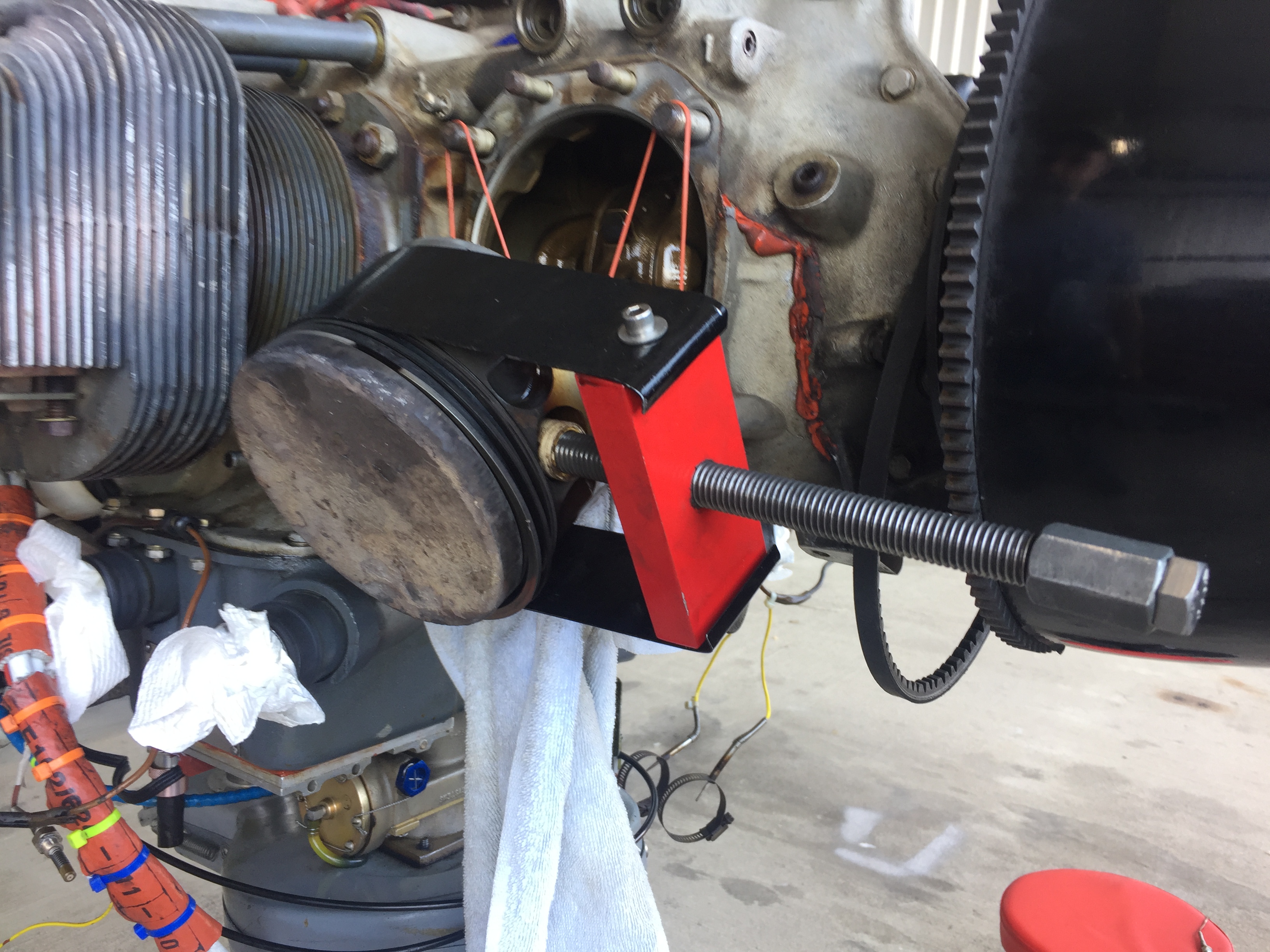
After some cleanup
The plate allowed me to torque the case through-studs, preventing cranckshaft bushing rotation.
Valves looking very good
Moderate scuffing means contact... not very good.
More light contact... still not good.
Here's what a new cylinders looks like
Oil beads on smooth surfaces, cross hatching retains oil for lubrication.
The cleanest these valves will ever be
More new to old comparison
🤔... wonder which one is new...
Comparing the new cylinders to the old one to make sure everithing's the same
Found a few differences with the casting, but not enough to cause any problem.
Cylinder's top side
Looks like the paint was burned off near the spark plug
Overhauling these cylinders would've cost $900 vs $1200 for replacing them.
An extra $300 each for all new metal sounded like a good insurance policy to me
Dirk showing me how to install a new cylinder
All new nuts facing correctly, and properly torqued.
Cylinder #3 was the first one I replaced after Dirk showed me how.
Cylinder #3
Not sure if this was rust or burned oil residue
Cylinder #3 removed. Installing the torque plates.
Used silicone O-ring preventing connecting rod damage
Two down, two to go.
And... I forgot to take final photos of cylinder #3, but I did get photos of cylinder #2 coming out, and going in.
Here I am removing cylinder #2
Removing the piston pin
A closer look
I never let any of the connecting rod ever touch the engine case
Time to install the torque plate
Torque plate installed, and silicone cylinder O-ring holding the connecting rod.
A few days later the plate is off, and the new piston goes on.
Compressing the rings before cylinder installation
Installing the cylinder solo is doable, but another set of hands would have been helpful.
Pushrods inserted (blue ziptie for intake, red for exhaust). Yes... I removed the zipties later.
One
thing I never knew before this experience is that there is a silicone
O-ring at the base of each cylinder sealing the steel part of the
cylinder against the aluminum engine case.
A new silicone O-ring installed at the base of the cylinder
The
valve rockers were cleaned up, and sent to an overhaul shop to be inspected. They were found to be within specs so I reused them, although I
replaced all of the rocker bushings. Interestingly, oil climbs through the
hollow push-rods under pressure, transfers through a hole in the rocker
arm and a matching hole in the bushing, and lubricates the rocker
bushings. Needless to say putting the wrong bushing on the wrong rocker
arm blocking the oil passageways would quickly lead to disaster.
Worn valve rocker bushing. A good reason to go all new.
Old rockers with new bushings. Highlighting the hidden oil passages.
#1 and #3 completed
#2 and #4 completed
At the opposite end of the pushrods sit the hydraulic lifters. These were cleaned up and reassembled.
Hydraulic lifter
Valve
clearance is managed by replacing the hollow push-rods with longer or
shorter ones as needed to achieve 0.028" to 0.080" of clearance. I had
to buy a couple of new push-rods and move a few more around to achieve
the desired result.
How to check valve clearance
Clearances (green), pushrod size (yellow).
I
stripped the paint off the valve covers, lapped the mating surfaces on a machining grade granite plate,
repainted the outside, and used new cork gaskets before closing the
top ends of the cylinders.
Valve covers repainted
Meanwhile, with the engine partially off its mounts, I was also able to remove the one magneto (Left) and have it sent out for the overdue (non-mandatory in an experimental) 500 hours inspection/rebuild.
Left magneto. Note the lack of clearance from the firewall needed for removal.
Had to partially remove the engine to get this guy out
Magneto parts that were replaced during the inspection
I also took this opportunity to remove and replace the engine rubber shock mounts (Lord mounts), another expensive but much needed item.
Supporting the engine to replace top rubber shock mounts
Top right engine shock mount
This one didn't look too bad
A set of four brand new shock mounts
Here's why you should check them
Shock mount goes between the engine case (gray), and the engine mount (white).
Another mount that needed to get replaced
Bottom left mount
Bottom right mount
Top left mount
Top right mount
I
did not trust any of the old rubber hoses not
to leak after 15 years of service, so I bought new cylinder head oil drain
rubber hoses, and new air intake hoses.
New drain hose ends
Oil drains from the valve cover area back to the case via aluminum tubes, and rubber hoses.
#1 and #3 oil drain tubes and hoses installed
#2 and #4 oil drain tubes and hoses installed
Old air intake rubber hose connector. All four were replaced.
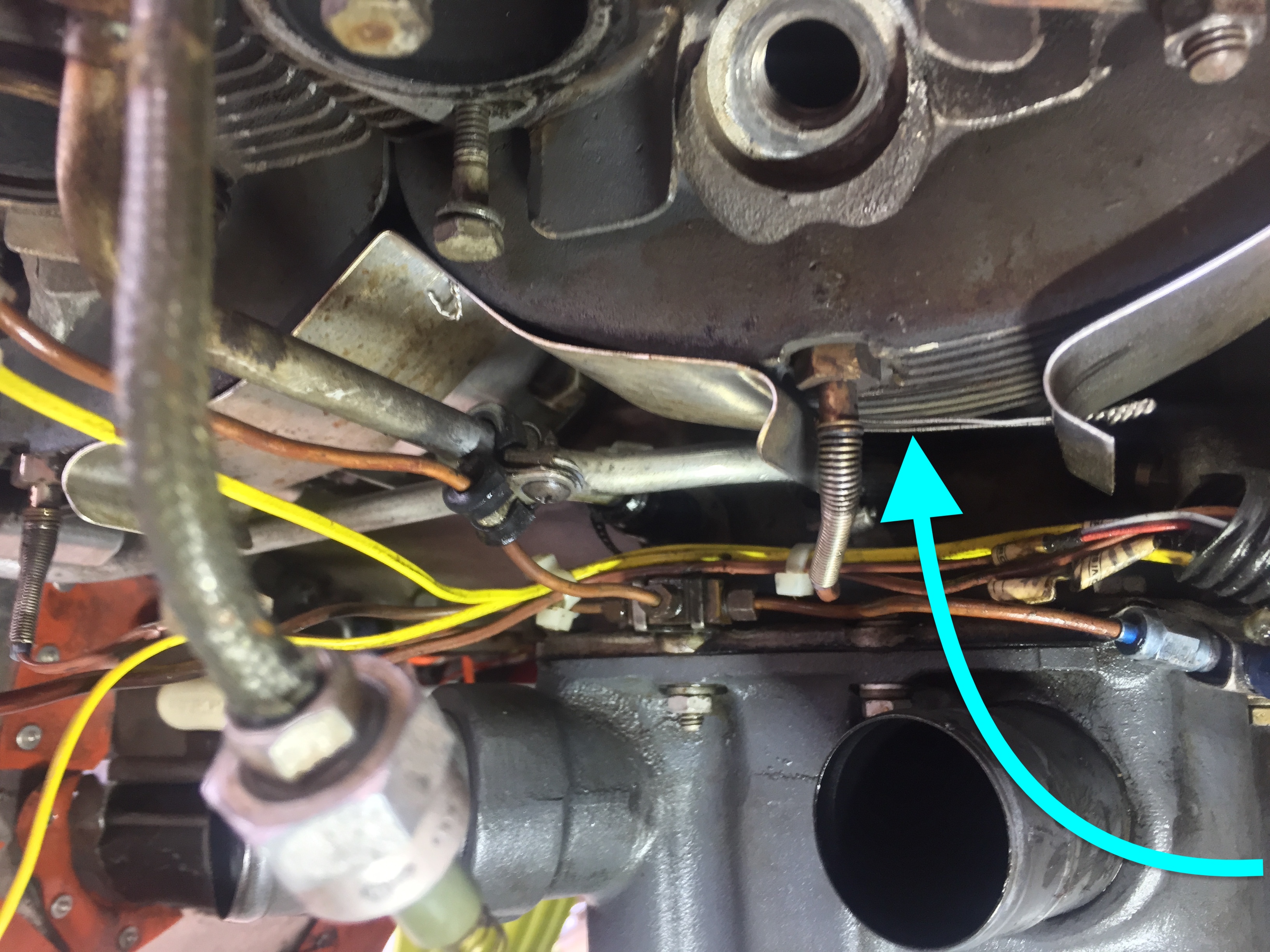
Looking
back at pictures I took of the air inlets to the head cooling baffles, the gap that admitted air
to the cooling fins appeared to be very small. This certainly contributed to the cylinders running hot. It turns out that the only directions
builders had at the time were related to the original
O-235 engine,
and not the O-320 engine Terry and many others started mounting on
Long-EZs around the turn of the millennium. With more power came more
heat to dissipate, and the original baffling proved to be insufficient.
In JT's case this caused the CHTs to run hot for over fifteen years, and
the evidence of excessive heat I discovered on the cylinders starts to
make more sense now.
#2 and #4 small cooling air passages
Small #2 cooling air inlet
Small #4 cooling air inlet
Small #3 cooling air inlet
Small #1 cooling air inlet
I
decided to open up both intake and exhaust slightly, based on later
research papers that were not available at the time Terry built JT.
I
also wanted to reduce the rattling and premature wearing of the
baffling material, so I used silicone baffling material glued to the
aluminum baffles.
Original baffles were metal on metal, and wore out.
Added silicone baffling material to prevent metal on metal contact
Silicone added to all baffles
Upgraded baffle installed
More baffle TLC in the rear
You get the idea
Eliminating rattling and wear is the name of the game
Baffles for #2 and #4 installed
Baffles for #1 and #3 installed
Because
Terry did such a great job making a very tight cowling, the proximity
of the exhaust pipes had been cooking the fiberglass in a few spots for
some time, so I put a thermal barrier to reduce future problems.
Can you spot the hot areas on the bottom cowling?
Upgraded the thermal barrier (bottom = old, top = new)
I used RTV sealant to glue the barrier to the cowling
The main two areas that were very close to exhaust pipes
Bottom cowling ready to go fly
The exhaust came very close to the fiberglass here...
...and here.
Top cowling had a few hot spots as well
I also ended up adding some silicone baffling material toward the back of the cowling to reduce cooling air pressure losses.
Adding silicone baffling material to help seal the top cowl
With the cowl on, this was an open hole for cooling air to leak out.
Now the hole is closed, and the cowl can more easily pressurize in flight.
Had the same issue on the left side
Left side fix
Fix seen from the propeller
While I was at it, I also insulated the electronic ignition coil wires.
I think the possible issue is quite evident here
Heat shrinking the ignition wires made me feel much better
Once the engine was back together, we followed Lycoming pre-oiling procedure (Service Instruction No. 1241C) then performed the thankfully unexciting first engine start, after which I concentrated on getting JT ready for first flight.
Uneventful first engine start (fire equipment and personnel off camera)
Breaking in the new engine was done by the book (Service Instruction No. 1427C), and JT has flown roughly 140 trouble-free hours since then.
If
I could add one word of caution for those doing the breaking-in of a
new engine, it would be to not take off with high cylinder head
temperatures (CHTs). I'd consider anything above 370º to be high
while on the ground. Personally I'd shut down the engine instead, let it
cool a bit, then restart and takeoff while the CHTs are still
relatively low.
With so many new internal parts lapping
themselves as the engine runs, it is possible for the CHTs to get pretty
high on the ground, and getting airborne only to find out that you are
already over-temping the engine (above 440º for Lycoming as per Mike Bush suggestions) while still low to the ground, requiring to pull the power way back, or even return quickly for an unscheduled landing.
Shutting down the engine on the ground will cool down CHT’s at a rate of approximately 20º/min, so even a 2 to 3 minutes pause will
yield big dividends on the first flight, and you’ll be able to run at
full power longer before reaching the CHTs limit (if ever). This
will enable you to get away from the ground faster, which by itself
increases the safety margin immensely, and creates more options should
anything else go sideways.
After
flying JT for some time, I started experimenting with incremental
modifications to the lower cowl ramps in order to even out the CHTs
among cylinders. Cylinder
#2 (rear right) was running hotter than the rest, so I allowed some air
to bypass the lower right ramp, to increase the amount flowing to the
back of the airplane.
Cooling ramps for cylinders #4 and #3 before modification
Holes added to cool down #2, and warm up #4.
The slots achieved the desired result, and the CHTs evened out.
In
conclusion, this was a very expensive lesson to learn, and definitely
one class I wouldn't have wanted to enroll in. In the end though I was
happy to have been able to learn how to do this type of work. This
experience will definitely make the connection between JT and me much
deeper, and a lot more personal going forward.
Great write up and photos. Just a couple of questions - what were the compression readings that the A&P wouldn't allow? How much did you open up the baffles to allow more cooling? And one more, how much does your A&P charge you for your annual CI?
Thanks. I can't remember for sure since it was over 5 years ago, and I am just slowly catching the blog up, but they might have been in the 50s or 60s. Same thing with the baffles, I don't remember what size they used to be, but I could always check what size they are now. I think back then most people went with what CP47 (page 10) described in 1986, though it was intended for O-235s. Around 2001 Andreas Christou wrote a pretty decent article somewhere that really changed my thinking on them. I do have a copy I could provide for you. As for the annual, It's been running around $700 with myself providing most of the muscle, but my A&P knows JT and me pretty well by now. Another friend brought his LongEZ over for the first time but couldn't help out, and I think his first one ran around $1200. Rest assured if there's something wrong with your plane Dirk will find it, and not look the other way, that can be good and bad depending how you see it. I prefer to know JT is good to go rather than one day find out something is wrong over inhospitable terrain. You know what I mean. Thanks for the comment, let me know if you need the articl. Ciao, Marco.


Great write up and photos. Just a couple of questions - what were the compression readings that the A&P wouldn't allow? How much did you open up the baffles to allow more cooling? And one more, how much does your A&P charge you for your annual CI?
ReplyDeleteThanks. I can't remember for sure since it was over 5 years ago, and I am just slowly catching the blog up, but they might have been in the 50s or 60s. Same thing with the baffles, I don't remember what size they used to be, but I could always check what size they are now. I think back then most people went with what CP47 (page 10) described in 1986, though it was intended for O-235s. Around 2001 Andreas Christou wrote a pretty decent article somewhere that really changed my thinking on them. I do have a copy I could provide for you. As for the annual, It's been running around $700 with myself providing most of the muscle, but my A&P knows JT and me pretty well by now. Another friend brought his LongEZ over for the first time but couldn't help out, and I think his first one ran around $1200. Rest assured if there's something wrong with your plane Dirk will find it, and not look the other way, that can be good and bad depending how you see it. I prefer to know JT is good to go rather than one day find out something is wrong over inhospitable terrain. You know what I mean. Thanks for the comment, let me know if you need the articl. Ciao, Marco.
ReplyDelete