Chronicling my Long EZ construction (and a few other things).
Disclaimer
This blog is for entertainment purposes only, and is not meant to teach you how to build anything. The author is not responsible for any accident, injury, or loss that occurs as a result of reading this blog. Read this blog at your own risk.
Friday, July 17, 2020
3D printing to the rescue
How time flies.
While I have not posted in awhile, rest assured I have not been dillydallying about, and have actually been working eight to ten hour days in the shop every day for the past four months. Problem is... I have been working so much I have had no time for anything else, including blogging, but we are about to change this right now.
When I installed the previous panel there were a lot of minor things I told myself I’d fix later, but later never came, and the proverbial can kept getting kicked down the road. Now that JT is at the house there is never gonna be a better time to make improvements big and small.
If you have ever considered purchasing a 3D printer but you weren't sure what you'd use it for, you are in luck because today I will show you just a few of the latest parts and jigs I have made for JT with my printer. Sure, perhaps I could have achieved similar results by injecting blood, sweat, and tears equity into the project, but there are already plenty of opportunities for that without creating any more than strictly necessary.
Let's take a look at what's a 3D printer good for...
HEADSET JACKS
One of the things that bothered me from day one was the location of the headset jacks. Not that there are many great places for them in such a small cockpit, but their position right in front of the control stick worried me about the risk of interfering with it. For that reason I have always begun every flight carefully routing those electrical cords away from “danger“, clipping them to the left seatbelt and left shoulder harness in a couple of places.
Headset wires routed away from the control stick
Of course, I have secretly dreamt of relocating those jacks for a long time, but never had a good answer for where to put them. So, with JT resting merely feet away in my garage, I chose to spent some quality time sitting in the fuselage trying a number of possible locations, categorizing them by ease of implementation and lack of obtrusiveness.
Pretty soon a clear winner surfaced. Apparently, I really liked the headset jack behind my right shoulder. This location turned out to be the most out of the way spot in the cockpit, and would allows me to never even see the headset wires during flight, let alone having to strap them to me. On top of that, I can now leave the headset in the right strake until I’m strapped in instead of tripping all over its wires as I get in and out.
One minor detail to figure out was where exactly to position the jack, and how to get the intercom wires to that location. In the past I have seen the triangular headrest itself used for that purpose, but I already had the fire extinguisher mounted there, so in the end I decided to design anew, then leverage the 3D printer to pull off my creation.
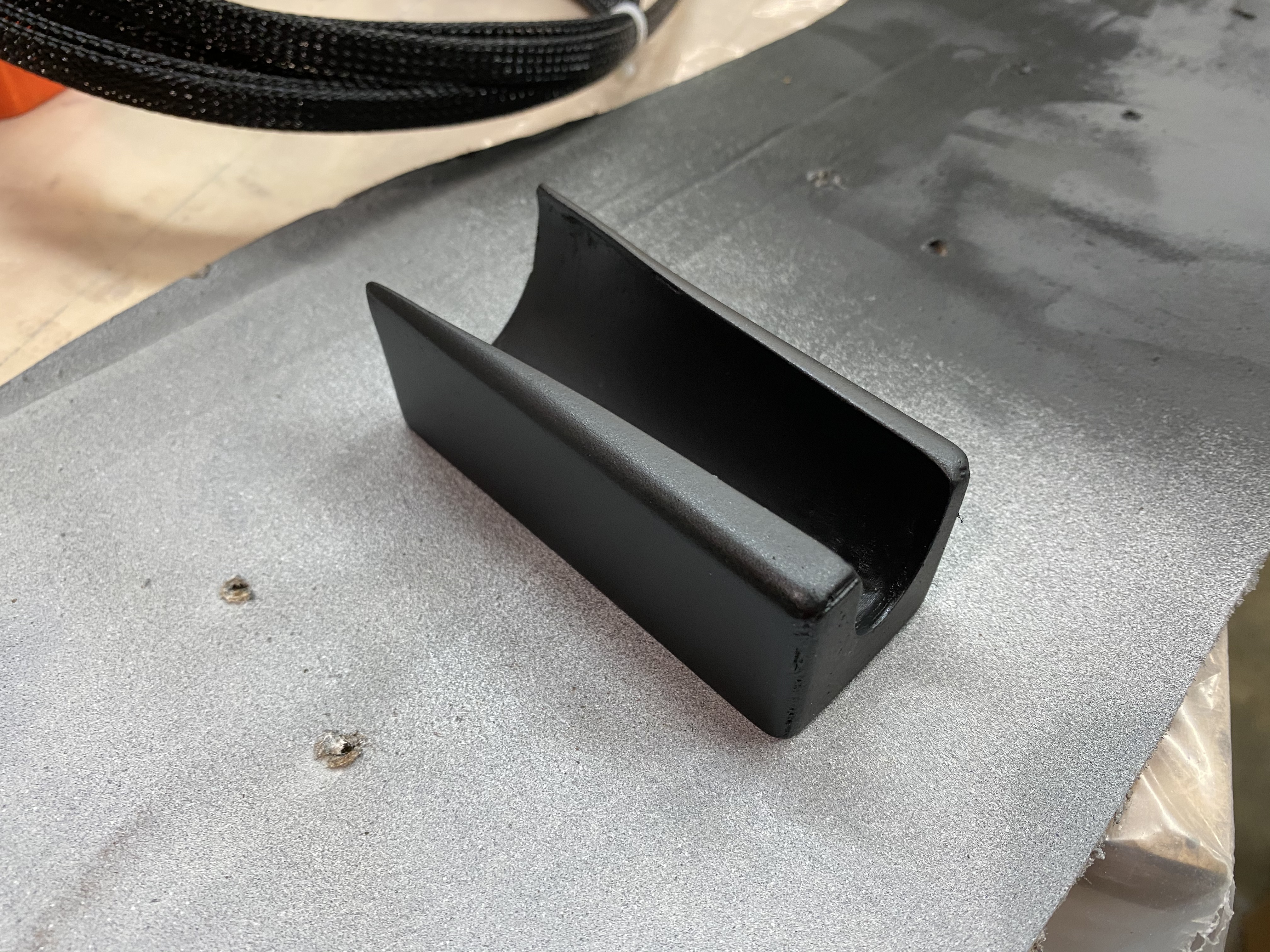
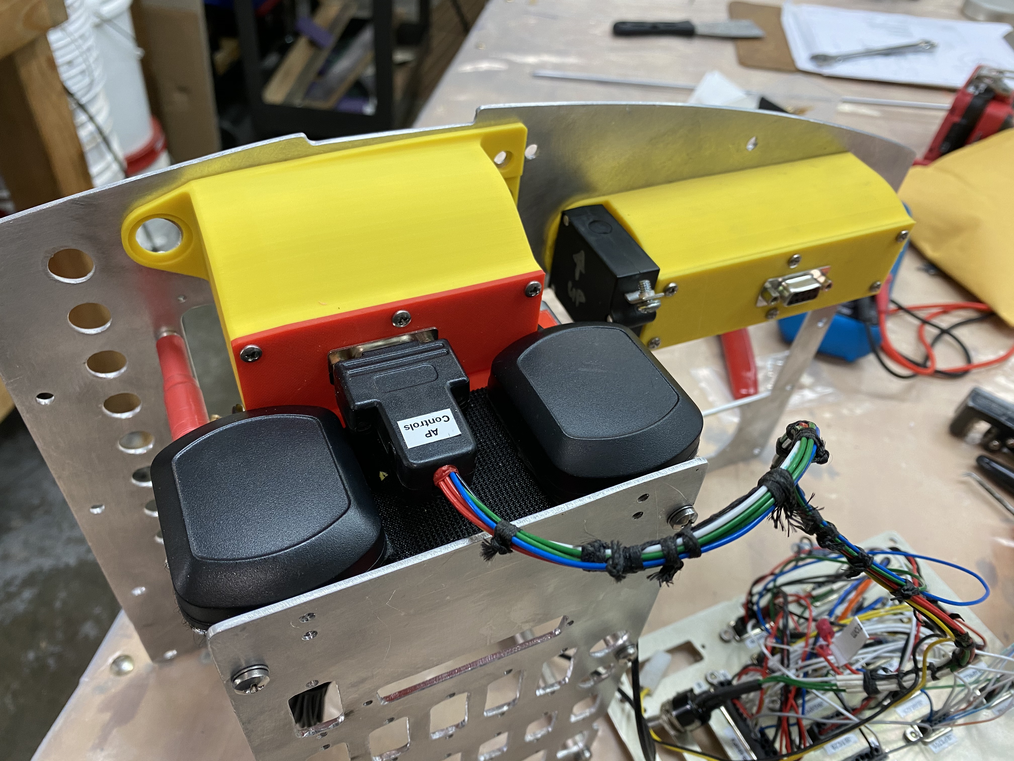
I present to you the new headset jacks mount…
Perhaps not beautiful, but functional.
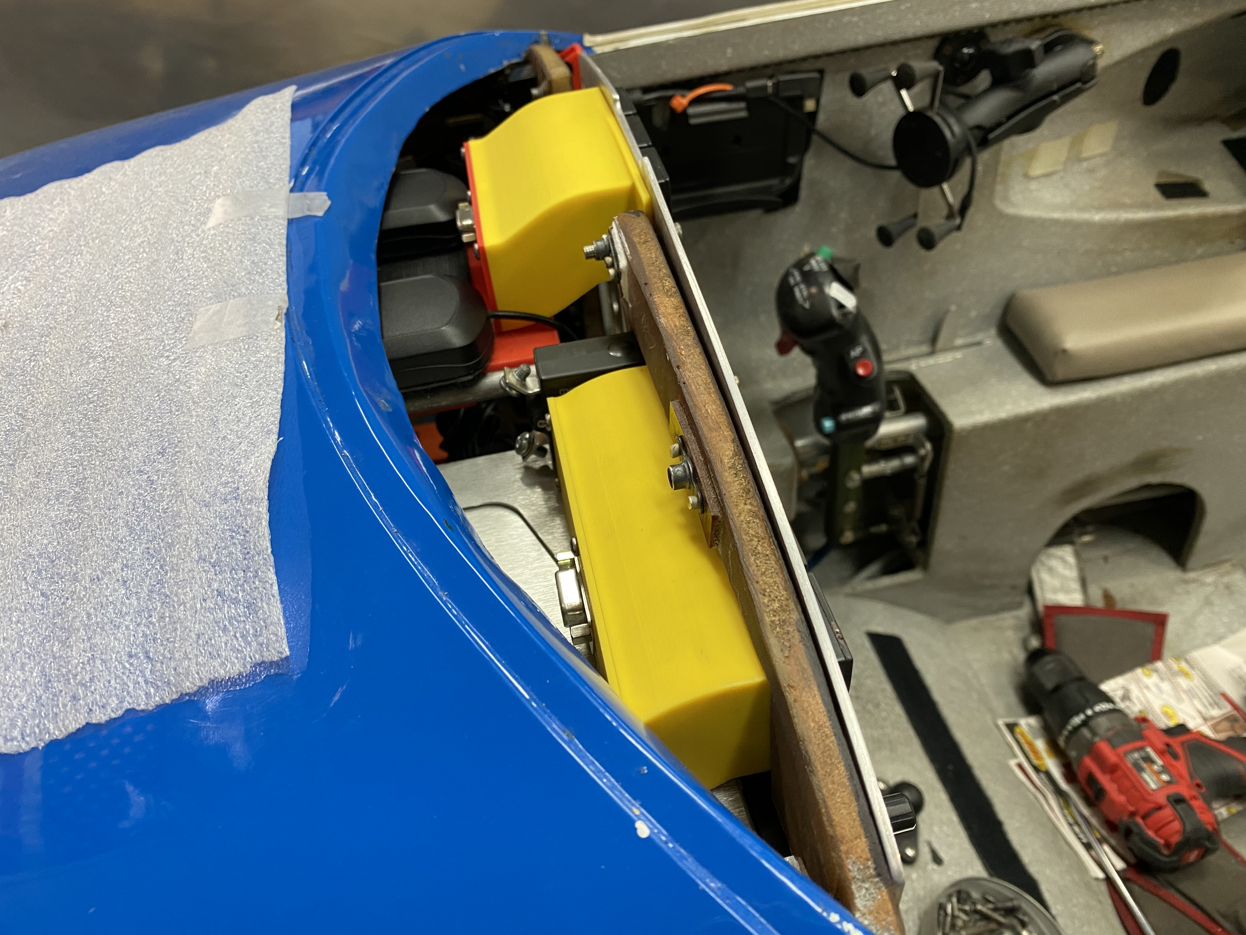
Right off the bat I had to modify my design because the canopy couldn’t close anymore, and I had to work around the seatbelt attachment point in order to be able to close the canopy without interference.
Talk about tight quarters!
Had to chop a piece off to make it work
Definitely unique
I like how the wires are out of the way now
Further in seat tests with the new jack mount in place confirmed my initial impression, and this will likely be the location of the headset jacks on my original project as well (if JT will ever let me get back to it).
BOSE CONTROL MODULE HOLDER
One other thing I wanted to find a better place for, was the Bose headset control module. With the headset jack in the new location, the control module was now laying down on the right armrest, and though this was still a thousand times better than where it had been before, something could and should be done about it.
I became a bit obsessed with finding a better place for it, and after seeing a dedicated control module holder online for $40, I chose to make my own, thus embarking in a new sub-sub-project.
Unfortunately, due to the organic shape of the control module, one cannot just start measuring it and hope to get anything even remotely close to it, believe me I tried. So I started researching 3D scanners, and found none I could afford. Checking the iPhone store, I tried a couple of 3D scanning apps, and eventually settled on one I liked... Qlone.
Using Qlone I was able to get a reasonably decent scan of the module on the first try, so paid $30 to upgrade to the full version that allowed me to transfer the STL file to my computer for further work with Fusion360 (CAD software).
Headset control module 3D scan
Digitally carving my scan out of a virtual rectangular extrusion left me with the perfect holder for the control module.
Headset control module holder
Should have made it aa little more symmetric
Very tight fit
Actually a bit hard to get in and out
Truth be told, a lot of reshaping of the inner surface was necessary with sandpaper in order to get a looser fit, but the process saved a ton of other type of work, so the tradeoff was worth it.
A few coats of Bondo to hide the 3D printed layers, and some black paint, and the holder was done.
First time I ever "post-processed" a 3D printed part
I velcroed it to the seat, very close to the strake, so that I’d have enough room left to relocate the fire extinguisher right next to it.
Actually, I think it looks really good there.
Why move the fire extinguisher from the headrest?
Well, the passenger in a Long EZ can’t see much outside but blue sky above (hopefully) due to the strakes on both sides, and the headrest up front. In JT’s case the fire extinguisher further impeded forward visibility. Removing the extinguisher from the GIB (guy/gal in back) line of sight sought to partially remedy this handicap. Turns out the halon extinguisher is now easier for me to get to with my left hand, and can do so without letting go of the control stick. True it is now out of direct reach of the passenger, but I believe the GIB could still reach it after undoing the seatbelts, or I could always pass it on back.
There is barely enough room for the both of them
Out of sight, but still within reach.
HEADSET JACKS WIRING AND HOLE DRILLING
One of the improvements on my to do list, was upgrading the audio wires in order to support the stereo sound the new audio panel is able to deliver. Stringing new wires for the passenger through conduits hidden within JT’s sidewalls was to be a royal pain, especially since such channels are already pretty full of other wires. However, using the old wires to pull the new wires allowed me to introduce this new capability with… shall we say… stealth, since no new wires are in direct view of the occupants.
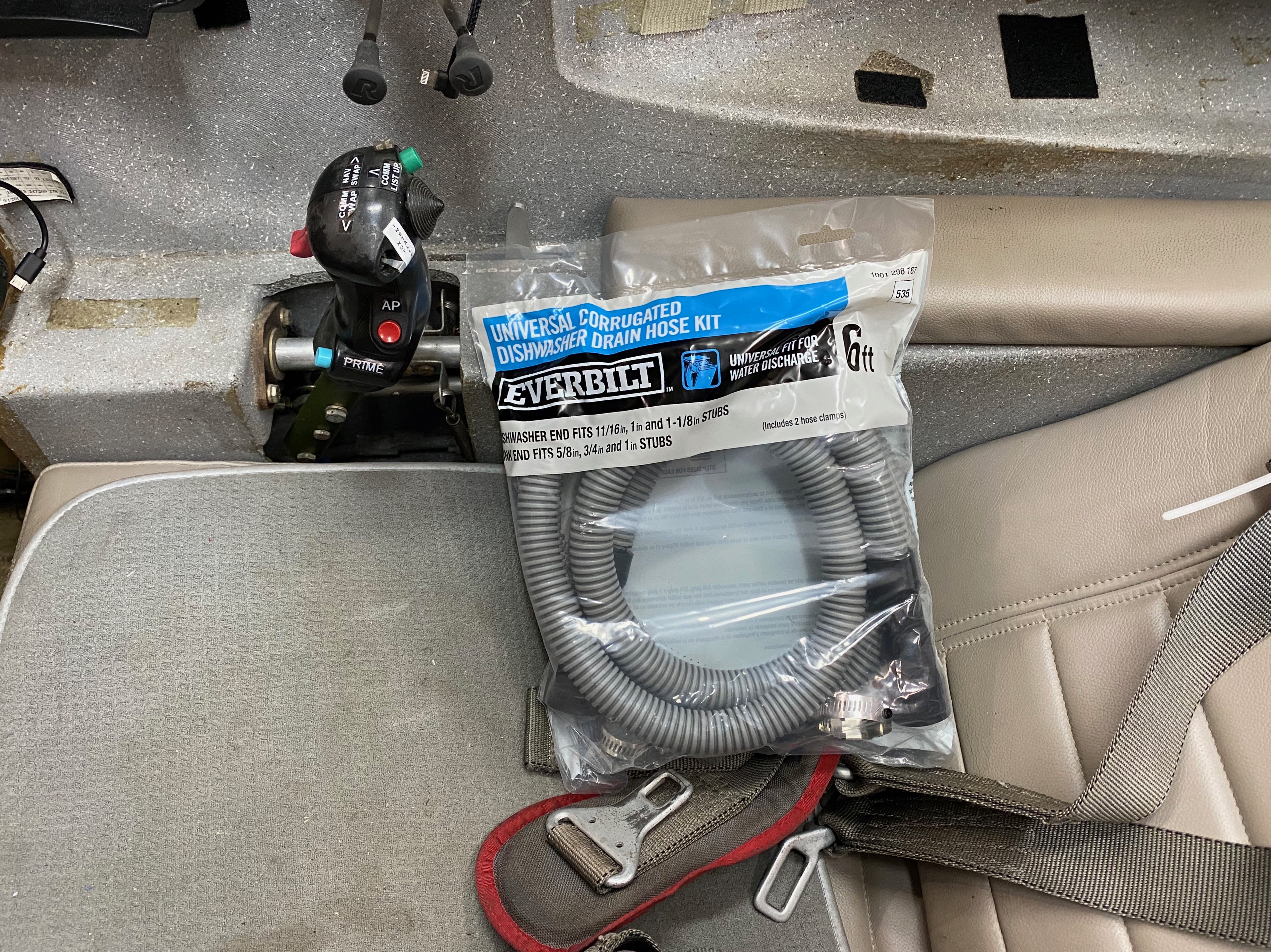
For the pilot’s headset wires, I used a dishwasher drain hose as a conduit for all new and old wires traveling below the right armrest. This proved to be a fantastic addition to JT. Cheap, light, flexible, readily available, and easy to cut with a razor blade, it offered all the qualities Long EZ builders look for, with the additional bonus of keeping electrical wires and fuel lines physically separated from each other while still adjacent to one another down the right side of the plane. I believe I don’t need to explain the potential for trouble here, should the two mix at the wrong time due to a leaky fuel line and a worn, perhaps arching wire.
This hose is just awesome, would definitely buy it again.
Opening up behind the instrument panel
Cut short to terminate behind the front seat
Still on major question remained unanswered… how to get the audio wires up to the new pilot headset jacks location. Obviously a hole had to be engineered into the seat to minimized wire exposure, mostly for looks, but partially to keep them out of harm’s way, but where?
I reckon I could get the bright white audio wires through the dishwasher hose all the way up to the pitch servo mostly unseen. To keep them that way the last foot or so, I’d have to drill a hole from there to the top of the back seat (actually the other way around) with the longest drill bit I owned. This hole couldn’t be vertical, and two separate very precise angles (forward and to the right) would be required for this to work.
If the fact that I had no way to directly measure these angles wasn’t daunting enough, I would also have to blindly aim the drill bit at an exit point I couldn’t physically see due to the location of the entry and exit holes.
True, I could just start drilling holes until one came out in the right location.
Nope, there was no way this was going to take place, not on my watch. One hole was already nearly one too many, so it would have to be the most precise hole I ever drilled.
I decided to throw as much modern technology I could at the problem, recreating that part of the airplane in CAD as precisely as I could, calculate all the angles, 3D print the biggest drill guide I could squeeze into my Zortrax, then go for it… one shot one kill… or forever live in infamy in the eyes of JT’s builder, Terry Lamp.
I decided that if I could get the exit hole to coincide with the USB charging point mounted behind the front seat, where wires are already reach, I could minimize the aesthetic disruption of white audio wires at near eye level. Although this was not strictly a necessity, it nevertheless became the focus for all my efforts.
Perhaps it would be better if I showed you what happened next…
3D printing to the rescue
Honestly, for quite sometime I thought I had failed at the process, though by fractions of an inch, until a viewer commented that…
“It's not the error in angle at the top that made the drill bit miss. It's that the drill bit was trying to drill (somewhat sideways) into an angled surface thereby pushing the drill bit point further down. In other words, the drill bit point wandered down. At any rate, keep up the good fight!”
Honestly, I hadn’t even considered that possibility. This made perfect sense to me, and restored my belief in the proper working of the cosmos 😉.
With the problem of the hole sorted out I got on with the wiring, but at this point I decided to also mount the passenger’s flood light control module and the passenger’s push to talk radio button in the same location.
The hole that was designed to carry two wires was now tasked with a so many more of them, that it got hard to pass them through.
insert seat back wiring
Passenger's lighting proof of concept
Passenger's lighting demo
In the end, the headset jacks and dimmer light boxes ended up playing well with each other, but I will combine them into a single print next time around to simplify the wire routing inside of them. As it is, I had to drill a hidden sideway hole through both boxes in order to allow the wires to pass through.
RELAY MOUNTING
My next task was to centralize and standardize my present and future relays demands by designing and mounting a relay rail in an accessible location, and stocking up on a few more of the same relay I use for running my “Low Voltage” warning light.
Of course this begun with recreating the relay design in CAD, and here I think I went a little overboard with the details, but... I had the time.
Electromechanical relay
Recreated in CAD
Back side
Circuitry highlighted in CAD
The rail design leverages a feature of this particular relay that makes it able to be captured by its head.
Don't need this many right now, but it's good to plan ahead.
3D printed rail
Relay sliding on the rail
Bottom is textured to be floxed on to a sidewall
I chose to flox the relay mount in an area of the nose where other relays lived already, so that all my relays will be in the same place.
Relay central
RELAY ADAPTER
That worked well until I replaced the one electromechanical relay I used for the warning light with a solid state relay.
You see, the Low Voltage light blinks on the ground with the battery ON and the engine not running (as it should), and the fast paced clicking sound of the electromechanical relay tied to the light is so sharp that could be heard in the cockpit, even from as far forward as I could get it in the nose, always creating a spastic sense of urgency, like… “Hey! I’m dying out here!”
While I always thought this was a useful aural indication that I was wasting time and loosing battery power, it also gave me a feeling of having to rush to get an alternator online. At times, like when turning the avionics ON to show off the panel for example, or getting the ATIS, I found myself always having to explain the meaning of the clicking sound to bystanders. The new solid state relay makes no such noise, at the expense of a new outer casing design.
Solid State relay had to have a different outer case
3D printing had to come to the rescue, again. I designed an adapter for the new relay that allowed it to interface with the "old" railing system.
I am not removing the relay rail off the plane!
I guess adapter it is!
You've got to love 3D printing!
Full house (for testing purposes)
WARNING LIGHTS ENCLOSURES
The Korry318 warning light I have used to replace other lights previously scattered about the panel have been a great success, so much so that now many other builders have started incorporating them into their own panels. I would be remiss if I didn’t give prompts to Wade Parton, the builder that found a source for them a few years back when he and I were discussing how things are done in the airline world.
With that out of the way, I wanted to address the Achille’s heal of this lights… the connector.
Why the connector? Well, the choice of connector in the back of the light works, but it is too prone to being unplugged by just tugging on the wires so, while my warning light system worked well, it was always was a bit of a flimsy setup, and I alway had to be around it.
Naturally then the next step in this upgrade would be to encase the wiring into a box that made interaction with the wires impossible. Make that two boxes, since I’m adding a set of status light for the GNS480 navigator/radio.
Let me skip the reasons for the various iterations of the design, something that always happens when finalizing a solution to a problem, and show you what I started with including all my failures, then go directly to the final version.
Before finding the right enclosure one has to first find all the wrong ones
Final evolution
From concept to reality
Enclosures in use
Test fitting the Korry-318 lights
Back side of the panel
Wiring scheme
Closing it up
The final product
Both enclosures installed
I used D-sub connectors on all enclosures
Enclosures are shaped that way because the nose of the plane lowers going forward
You can see the problem better from this angle
Final Approach Fix inbound 😂
Wiring detail
CHECKLIST HOLDER
This is not a new item in my cockpit as I have already enjoyed two previous version of this, but I wanted to add usefulness to the design by incorporating a pen holder within it. Figuring out what to do with a writing implement in such a tiny cockpit is just another little annoyance I thought I could mitigate with proper attention to the design.
Checklist holder version #1
Checklist holder #1 in left armrest (inside view)
Checklist holder #1 in left armrest (outside view)
Checklist holder #1 in left armrest (in the plane)
Checklist holder #2
Checklist holder #2 in left armrest (inside view)
Checklist holder #3 (CAD model)
Checklist holder #2 and #3
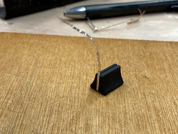
Pen clip stop
Pen clip stop in use
Trying a different pen style
Pencil testing
Checklist holder #3 in use
Will it fit an iPad mini?
It's a bit too tight
Perhaps version #4
BOOM BOX
One of the features of the new audio panel is the ability to drive speakers. I’n mot sure when this would be useful, but it seemed like a waste not to take advantage of it, so I purchased two laptop speakers on Amazon and designed a box that would hold them.
Boom box
Without the speakers
Ready to assemble
Final product
Boom box attache to the bottom of the radio stack (upside down)
RELIEF TUBE HODER
Because JT is not a new construction, I am alway looking into reusing existing features, like holes, or in this case a wire mounting tab.
What a relief!
Relief tube clip
Relief tube clip the way it should fit over a wire mounting tab
Ended up adding an offset wire mounting tab
Clip installed
Clip in use
Relief tube capture by the new clip
TAXI/LANDING LIGHT LINEAR ACTUATOR CONTROL BOX
This deserves its very own post, but since we are talking about 3D printed object, let me share with you pictures of the enclosure I made for this device. We shall talk about what its purpose is another time.
3D printed enclosure
Right off the printer, just before removing the support structure.
I decided to add a screwdriver holder to the lid
Linear Actuator Control board in its new box
LAC board wired up
Installed in the nose of the plane
Of course one needs not forget about knobs with which to move various controls...
See the slider located at the lower left corner of the panel?
10Kohm potentiometer
Making my own slider knob
Perfect fit
A little black paint and a strip aluminum tape
"All done!"
... or adapters that allow a smaller button to fit in a bigger hole originally meant for something else.
Repurposing the big hole where the buzzer was
A half an hour job
Secret project's switch in the buzzer's old hole
Plenty of throttle clearance
VARIOUS JIG SOLUTIONS
Probably not something one would think about right away are jigs that help with constructions or repairs.
Here's one such jig I dreamed up to help me patch a hole in CS5 and CS8. I cut this hole to install the wing bolts from the opposite side (front to back), and now it needs to be closed back up.
Round piece registers into the split round hole, and clocks the assembly.
3D printed assembly as seen from inside the spar
Ready for floxing, and once the jig is removed, glassing.
ADS-B ANTENNA STANDOFFS
After nearly twenty years of service the rubber grommets used to shock insulate the transponder antenna were pretty much shot.
Z-Flex, a Zortrax proprietary rubber like material was just what was needed in this situation. A few minutes in CAD, and I was exuding the new generation of rubber mounting isolators.
Four Z-Flex rubber mounts printed up in fifteen minutes
Rubber mounts separated and ready to be used
Rubber mounts fit perfectly
Antenna mounted on the left strake end
Another view of the antenna
I am sure by this point you have already dreamt up at least half a dozen project you could knock out with a 3D printer.
I say: "Do it! And may your life never be the same again". 😉


 Rubber mounts separated and ready to be used


Nah. I've got a neighbor across the street who loves doing stuff like this...
ReplyDelete😂
Delete