Chronicling my Long EZ construction (and a few other things).
Disclaimer
This blog is for entertainment purposes only, and is not meant to teach you how to build anything. The author is not responsible for any accident, injury, or loss that occurs as a result of reading this blog. Read this blog at your own risk.
Thursday, March 26, 2020
Ch 22 - Electrical/Avionics - Part 22
Panel #5 - Faceplate
You’d think I would have learned a thing or two about upgrading instrument panels by now. Yet, as I began cutting aluminum and shaping fiberglass, I was once again taken aback by the extent of the work required to get panel #5 done. Perhaps the fact that I was only adding a COM2(and an audio panel)lulled me into a false sense of ease.
I should have known better, nevertheless there we were… money had been spent, items were on hand, Pandemic sadly provided plenty of time off work, and JT was quite literally “in the house!”
I was out of excuses.
First of all I needed a new faceplate to hold all the goodies, then a new backplate (aka Junction Box) due to the new connections that would be required.
Cutting panel #5
A bit of a loose fit, but good enough.
For some reason the holes in the backplate were slightly bigger than they should have been, but precision was not necessary in this case, so I called it done and moved on. I will have to go backat a later time and figure out what happened, and also correct it in the computer in case there ever is a panel #6. 😉
If that wasn’t bad enough, I ended up bumping the faceplate while I was cutting it (a big no-no). You can see that happening 50 seconds into the video above, as I remove the MFD blank to prevent the torch from hitting it.
As a result, the Korry-318 indicator holes ended up ¼” further up than they should have been, as well as all the circuit breakers, the bottom of the panel, and the top as well.
Panel right off the plasma table.
"Doh!"
Worse was the fact that I didn’t fully understand what had happened until nearly a week later, and by that time I had already implemented workarounds in order to save the panel, like welding shut a few holes and recutting them by hand, or reshaping the top contour by hand with a file to include a slot for the canopy’s own NACA air vent.
Bottom right hole clearly out of place
Welding 6061 aluminum
Grinding the excess aluminum off with a 60 grit wheel
Using a 120 grit wheel to get back down to the level of the panel
After some manual sanding with a progressively finer sand paper
"E voilà!" After much filing to restore the hole
That was a ton of work, but now everything fits properly.
The taller panel required a lot of fitting and trimming session with the canopy closed
Below you can see a calibrated photo of the finished panel (hence the ruler) overlaid to the CAD file in Fusion360.
Minor differences between the CAD model and the cut panel are evident
Other than that, all cuts were of very good quality using the full 45A the Hypertherm Powermax 45XP is capable of, at a snappy 240 ipm (100 mm/sec). Dross was negligible, and dimensions right on the money.
Trig ADS-B fits in the panel right off the plasma table (👍👍)
The panel was then finished the old fashioned way… by hand.
Using the template Trig provided to mark, then drill the holes.
Mounting holes worked well, though I wish I had mounted those units a little lower now.
On top of all my previous mistakes, I also built panel #5 in CAD using a practice file I had forgotten to delete, which had slightly different contours. This forced me to have to trim both sides of the panel both in real life, as well as in CAD.
We are going commando on this panel!
Oh well, panel #6 will be right on size and shape from the get-go.
Meanwhile, here’s what I had thus far…
Complete instrument panel #5 skeleton (old harness to the side)
Back view of the unit
Making sure everything fits while outside the plane
A glamour shot with the radio and audio panel
My panel design concept specified that the panel must be easily removable as a unit, not so the radios. Naturally, the next step was to devise a way to permanently mount the radio trays to the airplane structure. Unfortunately, for this to happen more fiberglass had to be sacrificed.
"Hold still JT. It'll hurt for just a minute."
Fitting the GNS480 tray to the plane
Checking how much space I've got to play with.
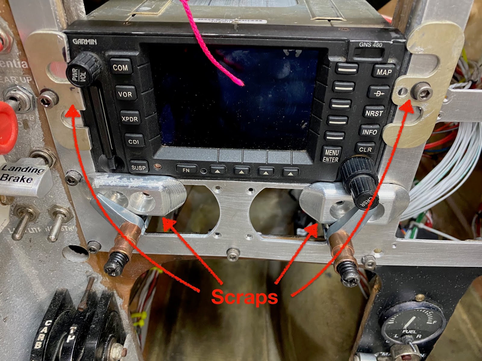
At this point, in order to match the Trig's COM#2 and ADSB flush look, I decided to also mount the GNS480 and audio panel flush with the panel.
Scraps holding the radio flush with the panel while assessing brackets mounting options
This looks pretty good (to me)and fairly unique
I think the flush look turned out quite well, and gives a slightly more open feel to an already cramped cockpit. Were I to do it again though, I wouldn’t go though all the trouble since I spent five days reworking the brackets over and over in order to get the spacing just right.
Replaced the left fiberglass bracket with a new aluminum one
Connected both trays together
Added thickness to the right bracket to move the radio further into the panel
Added fiberglass thickness to the left bracket for the same reason
Added thickness to the inside of the right bracket to move the radio slightly left in the panel
Turning a scrap aluminum bar into a hole duplicator for the panel
Using the hole duplicator to transfer bracket holes to the fiberglass panel
Floxing fiberglass irregularities, later to be sanded flush for panel #5 to fit correctly
Fiberglass structure ready to accept panel #5
That was a lot of work just to get an esthetically pleasing outcome. Fortunately (or not), time is plentiful under the current global circumstances.
The next item on my list was the new Korry-318 cluster above the radios.
Addressing this feature required a further fiberglass sacrifice turning what was left of the old fiberglass panel into nothing more than a nut-plates holder. The lost strength is more than made up by panel #5 metal structure, although in a perfect world I wished I had been able to preserve more of the original fiberglass bulkhead.
"I hate doing this to you JT, but it's for your own good."
There we go, almost everything fits now.
At this point I realized that mounting some of the switches in the location I had previously planned for them, required even more fiberglass cutting, so I decided to change their location. This required either a whole new panel, or another go at the old one with my magical hole eraser(aka TIG welder).
Luckily for me 6061 aluminum is weldable and pretty forgiving, provided you surgically clean everything. Better yet, one doesn’t need to be a great welder as long as he is a good enough grinder. 😂
Swapping holes around to save the glass
Holes welded shut
After some grinding action 😉
After more sanding
With the instrument panel rescued once again by elbow grease, I moved the holes to their final location... hopefully.
Deciding on new locations for the holes
Final, though slightly less than ideal, switch locations
Now that the faceplate is finished let’s take a look at the new one standing next to the old one…
Panel #5 (left)next to panel #4
Quite a change, isn’t it?
Next time we will dust off the 3D printer to make some new parts, and then start wiring the new panel.


No comments:
Post a Comment