Disclaimer

This blog is for entertainment purposes only, and is not meant to teach you how to build anything. The author is not responsible for any accident, injury, or loss that occurs as a result of reading this blog. Read this blog at your own risk.

Wednesday, September 02, 2015

Center section spar - part 1

The jig (15.5 hrs)

Welcome to chapter 14.

This is a very important chapter, because I will be building the center section spar, the real backbone of the airplane. Most of the important parts of the plane like wings, fuselage, and engine connect here, so it is paramount that it is built correctly.

The wing spar is basically a rectangular box with swept ends, and it is initially assembled facing upward in a wooden jig. Get the jig wrong, and your spar will be just as wrong, so it behooved me to invest as much time and effort as necessary in doing it right.


The main spar jig (link to the 3D interactive jig)


One of the clues to how important this jig is can be gleamed by the dimensions specified in the drawings. All dimensions are given to the hundredth of an inch!


Measure with a caliper, cut with a table saw!

I am no carpenter, but I’d be willing to bet that not a lot of carpenters make pieces of furniture to that kind of accuracy. Nevertheless this is our path forward, so I’ll be striving to be as accurate as possible.

Normally, I would have gone to the store and bought some cheap plywood to erect this temporary structure, however I still had some suitable scraps of cabinet-grade plywood around the shop, leftovers from building the heated epoxy box and the fiberglass cutting table. These had been sitting around for 4 years awaiting some good use, and they were already paid for, so they were called for duty. They will be suitably reused in other parts of the project when this jig is no longer needed.

The only issue with this plywood was that it wasn't 100% straight (more like 95%), but I decided to use it anyway, and to take care of it during the assembly.

Task #1 was to recreate the exact measures from the drawing onto the wood, cut it as close as possible to the lines, then sand where necessary.


Following the pencil line with the right edge of the fat part of the saw blade's teeth. Yikes!

Manning the table saw


It helps to have a lovely assistant for tasks such as these…


Thank goodness for the help

To avoid having to draw and cut everything twice, I doubled up the plywood, screwed the two pieces together, and cut along the lines with the help of a straight edge.


Two boards screwed together

Same two boards after a couple of cuts

This method was not as precise as I had hoped, and left a 0.047” (1.2 mm) saddle, that I later filled with Bondo, and sanded to flatness heaven.


This edge will be used to shape the foam to size, so it needed to be repaired.


To help hold the vertical back piece D (I actually used two half pieces for this) perpendicular to the table, I bought some 90 degree steel bracket. 


Bomb proofing the jig


They turned out to be a bit off right out of the box, but after a good beating they changed their minds and decided to get on with the program.


This might be good enough for a bookshelf

There we go, all better now!


Before erecting part D, I attached the two halves together on the table, with the help of a straight edge.


Attaching the two D halves

Joint closeup


While I was at it, I screwed 2x4s on its back to ensure it would remain straight once vertical.


More recycled lumber in use, the long piece is from "The straight tower of Pisa", the short 2x4s are from the fuselage rotisserie 

That's what I'm talking about!


Next, I cut and assembled the remaining pieces of the shelf (A, B and C), and the supports (E,F, and G) that went under them, then performed the Bondo magic trick.


The jig and its components

Adding Bondo to level the shallow saddle

Sanding the Bondo flat

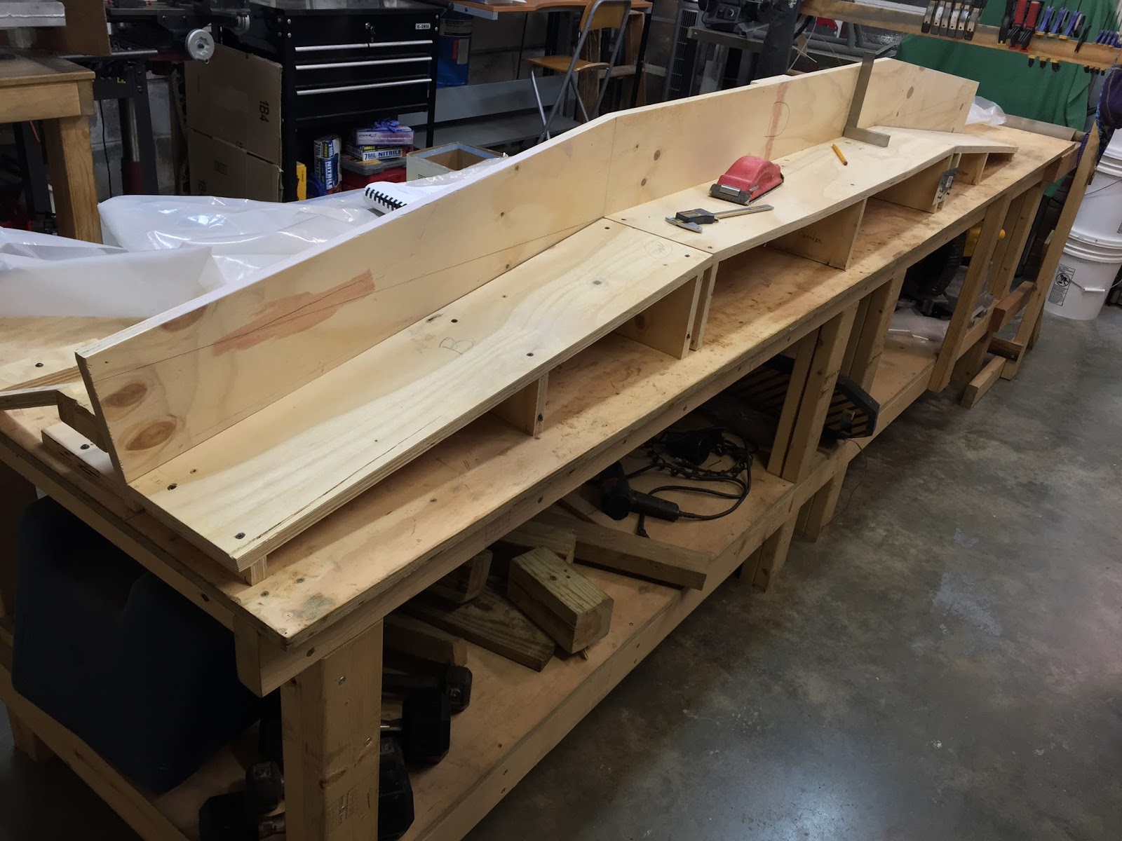
The completed jig


Everything got screwed to the tabletop, with enough screws to be able to withstand a nuclear blast.


This jig not going anywhere!


I had to do some minor tweaking at the very ends, where the plywood was ever so slightly out of square, but it was pretty easy to do, and it was all brought back to resemble a cartesian dreamscape.


Minor adjustment

Both ends needed a tiny help


Sunday, August 30, 2015

CNC mill conversion - part 25

Spindle light

When my talented friend Phil talks to me about his ideas, I listen carefully, and when he told me about a microscope LED light on eBay that might work as a spindle light, I easily parted with $20. 


LED microscope light


The light turned out to be very bright, and that’s a great thing since I’ve often been forced to hold on to a flashlight while milling. It might be because of the mill's location, or perhaps the partition I erected to keep swarf at bay, but my setup has not been the best as far as ability to see what's going on.

Until now… that is if I could figure out a way to attach it to the mill. See, the root of the word "spindle" is… spin (duh!), and since it does spin, this makes it impossible to attach a light directly to the spindle itself.

After spending a little time looking up to the mill’s head from below, I had the idea of replacing one of its plastic cover with an aluminum piece that would be be concentric with the spindle, serve as a mount for the light, and not interfere with the spindle rotation. 


Plastic cover

Plastic cover original position

Mill's head with the plastic cover removed


After reverse engineering the plastic cover, as well as the microscope light, I came up with a drawing of the proposed mount made with Fusion 360.


Approximate dimensions for the MicroMark mini-mill

This is what I will be trying to make

Now, these dimensions are the best I could come up with while working upside down with a caliper, but should be close enough to make it work.

During a lull in my fiberglassing activity, I got on with the latest mill improvement.


Machining the spindle light mount


Unfortunately, I did have some issue with the mill. Because I still haven’t wired the limit switches, I might have accidentally over-traveled the X axis just before this job, and possibly dropped a few ball bearings from the ball-nut, as a result my milling of circles was off by as much as 0.040” (1 mm). Crap! 

Luckily for me, this piece will never be seen again after today, and with the the location of the holes being the only critical part of the design, I quickly ran it by the lathe to make the mount round again.


Not pretty but it fits, and that's all it matters.

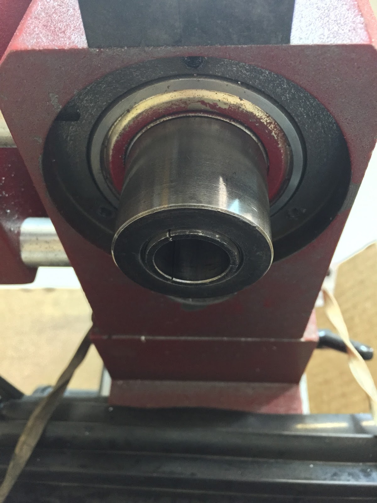
The spindle is unaffected by the mount


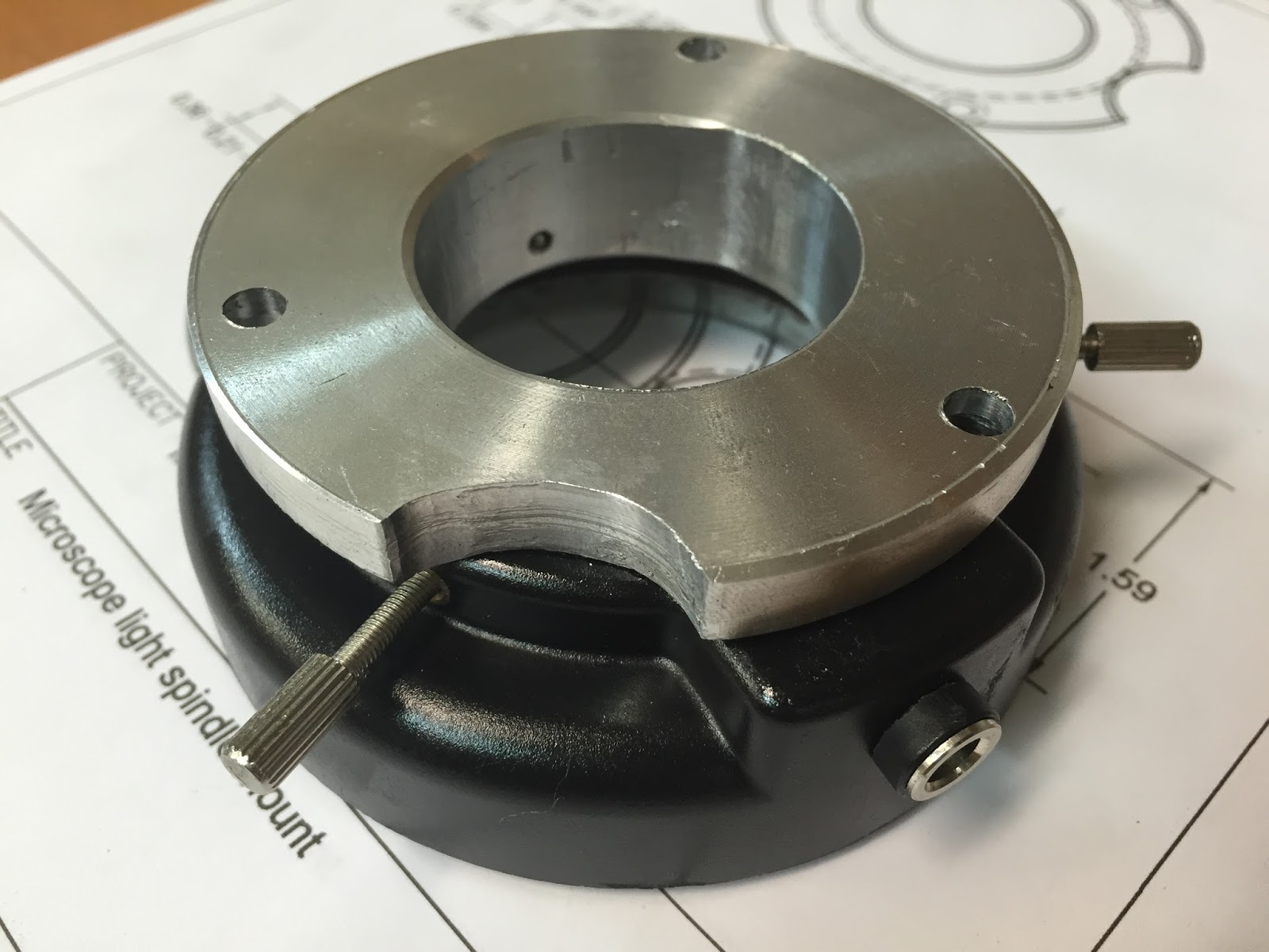
The light fit snugly on the mount. Thumb screws were not necessary except to prevent possible sliding movement due to vibrations.


Nearly a press fit, the light easily stays on without screws.

Light on the mount, but off the mill.

Back side


So, I ended up radially drilling (#40) and tapping (3-0.5 metric) three holes into the aluminum mount to match the thumb screw locations.


As I said, this is just a light mount, let's not get overly complicated here.

Smallest metric tap I have

Three holes drilled and tapped

Assembly side view


Obviously, one would not want the screws to protrude through the mount and end up rubbing the spindle, so I made sure to stop when I saw the end of the tapered tap reach the inner diameter of the mount. This ensured the screws would be confined to the mount itself at all times. 


Thumb screws unable to protrude into the spindle space

Tool changes are still as easy to do as they were prior to the modification.


Spindle light is up and out of the way


Overall I am very pleased with the results of this upgrade. 


I might need sunglasses now


Though I was concerned that the tool would cast a shadow right over the part to be cut, this turned out not to be the case. The whole cutting area is now flooded with so much bright light that I can even see what I’m doing now!


No tool shadows present within the work envelope


UPDATE:

It turned out that the lack of precision was due to a bolt that loosened up due to the vibrations that occurred when I took full depth of cut passes. The bolt in question snugs the Y ball-nut to the table, and after tightening it the problem disappeared entirely.

Here are the latest backlash numbers...


No issues here!


Tuesday, August 25, 2015

Nose and nose gear - part 30

Hinge box (11.3 hrs)

One pretty common complaint heard in Long EZ circles is that of cold legs. A couple of reasons for this are the inability of the typical heat exchanger to send warm air from the rear mounted engine all the way up to the nose of the plane, and the air leak prone nose compartment.

Over the years builders have come up with all kind of creative solutions for this common issue. My approach would be to seal up as many holes as possible first, then worry about possible heating options.

Looking at the upside down nose of my Long EZ, one obvious source of unwanted high pressure air is the nose gear hinge area. The gaping holes left there look capable of delivering cold air right on the pilot’s legs.


"Dang, you can almost see the back-seater from here! "


My friend Beasley had a very interesting approach to sealing this area, by using a small forward-hinged spring-activated door in front of the hole. 


The forward hinged door is able to slide on the strut cover as the gear leg moves


His approach was made possible by the omission of the foam wedge that went right in front of the nose gear hinge. 


This foam piece is a faint attempt at closing one of the gaps


Since I had already installed it, I had no real good place for a hinge, and had to think of a different solution. One thing I couldn’t understand was the reason for the hole to begin with, so I thought about sealing it shut from the inside.

Grabbing some ever present scraps of foam around the EZ shop, I whittled them until they fit.


Getting the foam scraps to the right shape


Foam scraps closing the hinge hole


One other advantage of this modification, was the boxing on the fifth side of the forward space between NG30s, leaving a small enclosed space that could be handy to store a few tools, or a spare tube.


Foam scraps as seen from inside the nose compartment


I removed the foam pieces, glassed them on both sides, and tested them again.


Proceeding with the modification


After more fitting and sanding


I'm starting to like where this mod is going


At this point I reinstalled the nose gear, and finding no interferences anywhere, I went on to the installation phase.


Behind the microscope LED light, the Dremel is removing foam and micro for a flox corner joint.


Given the small confines, the Dremel was used extensively in this area.


Foam and micro were also removed on all four sides of the horizontal piece


Three sides were filled with flox, then the piece was inserted carefully in place


Same piece curing, as seen from inside the nose compartment.

The next day I added BID tapes just to secure this first piece, and make sure there would be no gaps for air to get through.


Small BID tapes


Sealing the horizontal piece


Same thing one day later

After flipping the fuselage right side up, I started working between the NG-30s.


Getting ready for a flox corner


Flox sandwich


To be cleaned up


Tying things together


Peel-ply over BID

In the morning, after a little cleanup.


No air is coming through here


My feet would have rested right next to the drafty hole

So, one might ask... What's the point of sealing the holes by the hinge when you can clearly see another gaping hole right behind it?


"Yeah... what about that hole!"

You would be talking about the hole through which the nose gear actuator operates. 


Well, you've got to have that hole. 


The good news is that the flange I added to the front of the entire nose strut will completely seal this area in flight when the nose gear is retracted. I might get a little indirect air for a couple of minutes on takeoffs and landings, but I can live with that. 


I have more ideas on how to seal the remaining space between NG-30s in a way that will not impact the actuator mechanism and still be removable for maintenance, but we'll leave that for later down the road.  


Nose gear hinge "box"

It's a tight squeeze in there now

Looking toward the right NG-8

I'm very happy how this mod turned out
The struts operates just fine, and the cold air shall remains outside.
Before and after