Disclaimer

This blog is for entertainment purposes only, and is not meant to teach you how to build anything. The author is not responsible for any accident, injury, or loss that occurs as a result of reading this blog. Read this blog at your own risk.

Friday, August 16, 2013

"Tooling up" - TIG welding


Introduction to Tungsten Inert Gas welding

One of the problems with making your own roll-bar is that, in order to fit correctly, it needs to be custom made, and since taking the fuselage to a welding shop would be rather difficult, I decided to take the welding shop to the fuselage by learning how to do it myself.

Let’s just say that there are at least 4 main ways to weld metals together: Oxyacetylene, Shielded metal arc welding (SMAW) aka Stick welding, MIG, and TIG, and that all of them are somewhat suitable for my purpose, some are however more so than others. 

The reason I chose the TIG process is because it produces better looking welds without spatter or smoke, the heat affected zone is very small, minimizing distortions, it does not employ any flammable or dangerous gasses, and is virtually silent.  

But what is TIG, you might ask? 

TIG stands for Tungsten Inert Gas also known as GTAW, or Gas Tungsten Arc Welding, named after the non-consumable tungsten electrode that carries electricity through the middle of the torch, and the Argon inert gas that flows through the torch head flooding the area to be welded, displacing the atmospheric oxygen. 

A grounding strap electrically bonds the part to be welded to the welding machine, thus an arc is produced when the tungsten is at an appropriate distance from the part, and the trigger is pulled (or pedal pushed). Current is carried through the ionized gas and metal vapors (plasma) in the form of an arc that can reach temperatures as high as 10,000 degrees.

As a puddle of molten metal forms on the surface, a filler rod is introduced to join the two parts at the gap. 


Although I’ll be welding 4130 chromoly steel, one important thing to be aware of is not to use filler rod marked as 4130 for aircraft construction, but only one of the those listed below, in order of desirability. These rods give the joint much more strength, in the order of 80,000 PSI.


I'll be using #1 in 1/16" and 3/32" thicknesses on the roll-bar


In case you are wondering what difference the Argon gas makes, look at this experiment I ran...


TIG welding with Argon gas

Tig welding without Argon gas


There are a few drawbacks with TIG, namely the higher cost of the machine, and the slightly more difficult skills to master, having to coordinate a torch in one hand, a filler rod in the other, and an accelerator like pedal under one foot.  

My friend Wade and I have been discussing pros and cons over the past year, and I have diligently been educating myself by studying anything having to do with TIG that I could put my hands on. 

The source of TIG training I enjoyed the most are Mr. TIG’s videos on YouTube. Mr. TIG, aka Wyatt Swaim, is a professional aviation and Indy race car team welder with great knowledge, and personality. He’s got a ton of production quality videos on YouTube, and you can see them for free at http://www.youtube.com/user/Welddotcom 

Getting back to the story... 

One day Wade surprised me by buying a inexpensive 200 amps Simadre Chinese inverter unit (less than $400 on eBay), capable of TIG, Stick, and Plasma cutting, at 110 and 220 volts. 


Capable 200 Amps Chinese unit

Back of the Simadre. Note the 110/220V input.


While initially thinking that Wade had wasted his money on some cheap Chinese knock-off, I have had to change my mind completely in its regards after having been able to use it for the past month, and I am now very impressed with this unit.

Hard to believe, I know.

Since Uncle Sam sent Wade to the “sandbox” for one year, he generously offered to loan it to me until he gets back (how can you refuse a friend like that!?). So, I picked up a welding cart (very nice), and a welding table (cheap crap) from Northern Tools...


Excellent welding cart

Not so great welding table


... and set up my welding corner away from flammable materials.


My welding corner


I purchased two boxes of scrap 4130 assorted steel tubing from Wicks, and used an online Tube Coping calculator  to produce paper templates for cutting dissimilar tubing at various angles, and offsets.


Getting ready to cut some test tubing

Cutting the computer generated pattern

Cutting along the line

Rough cutting done

After a few grinder passes

Test fitting


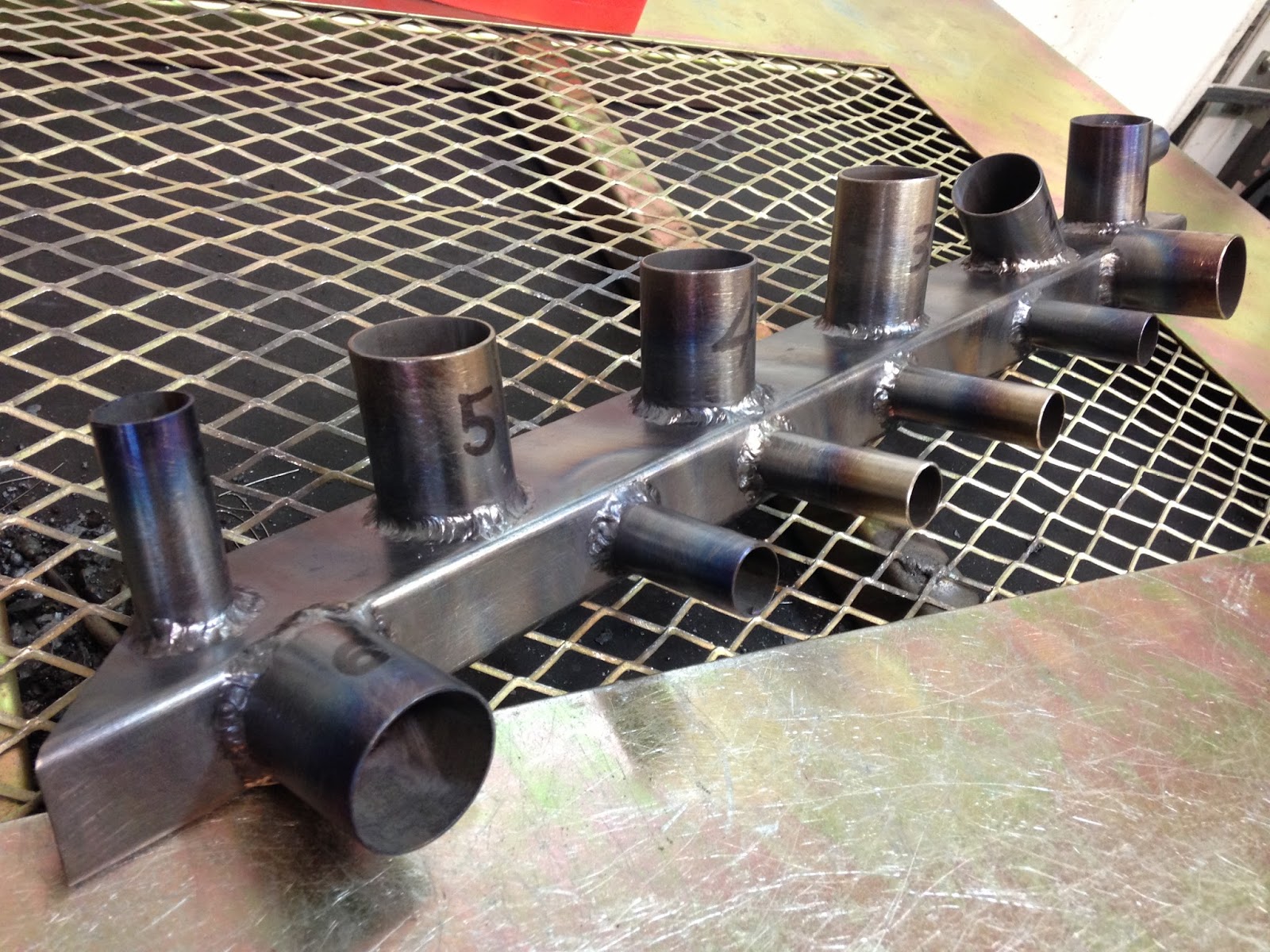
I spent a decent amount time practicing my skills on all kinds of 4130 thicknesses, going from 0.250” to 0.035”, and here are my practice welds... the good, the bad, and the ugly...




Welds on 0.035" (0.9 mm) chromoly tubing


Welding practice video


While my welds are not very pretty, they are perfectly acceptable, so I am planning to start welding the roll-bar next. 


Wednesday, August 14, 2013

Main landing gear - part 1


She's got legs... (16.2 hrs)

Welcome to the landing gear construction page, where you’ll be a witness to how I turned the basic fiberglass structure into a landing gear.

Let me first introduce you to the basic components, the main gear bow, and the nose gear strut.


Main gear weighs 22 lbs


A bit dorky I know, but since the FAA will want to see pictures of me during the construction process (in order to prove I actually built this thing), you’ll have to suffer through a few bad photos of me as well.

I will focus on the main gear today, and leave the nose strut for a later date.

Let me answer a few questions up front... 

  • No, I did not build the bow, I bought it from FeatherLite. 

  • No, they don’t have a website, these guys are old school, and they have been making the gear for nearly 30 years. 

  • Nope, no one else makes the gear and it would be too big a project for me to make just one. 

  • Yes, this is a major choke point in the supply chain, and you have to order it as soon as you can, because it takes a long time to make.

  • Yes it is expensive. $730 shipped for both gears.

As received, the gear still needs a lot of attention though, and the first step is to sand the shine off of it, because more UNI is in its future.


The table top worked quite well holding the gear bow for sanding


That was easier said than done though. Sanding cured fiberglass is very difficult, and I was having a hard time making progress.


This step was too slow, and too painful.


Thirty minutes later, I knew this wasn’t going to end well for me and, suppressing the purist in me, I enlisted mechanized help.


This is the way to go... carefully!


I felt very guilty about this choice, for about one second. The truth is that in the next thirty minutes I was nearly finished sanding. The sander worked out great, and the vacuum did an excellent job sucking up all the tiny strands of itch producing fiberglass.


Contraption holding gear bow like a Texas long horn hood ornament


Less than an hour later I was already planning my next step.

The main gear bow needs to be completely enclosed within 8 layers of crisscrossing UNI, 4 of them applied from the trailing edge, and 4 from the leading edge. Because the gear bow is so long, the layup is split into two sessions, one per leg, for a total of 16 smaller plies.


The big idea


Gear bow cross-section


These plies are cut at a 30˚ bias from a 38” (97 cm) wide UNI roll.


Fiberglass cutting plan


Cutting the glass


Measuring and cutting the strips of UNI took a long time, but eventually I had them stacked up and ready to go.


3 lbs (1.4 kg) of fiberglass will require 3 lbs of epoxy


The important thing to remember at this point, is to flip over every other ply, to make sure the threads crisscross.

With the table cleared up, I put 3 screws into the top, mixed some 5 minutes epoxy with flox, put little dabs of it on the head of the screws, and attached the gear to the screws. This is done to elevate the gear bow off the table, in order to better apply the UNI in the next step.


Gear bow epoxied to screws


These plies of bid are so big that merely handling them is quite a challenge, so I decided to pre-preg them, to make my life easier.


a full cup of epoxy (0.78 lbs, 350 gr) wetting 350 grams of fiberglass (4 plies)


Plastic sheet folded over the fiberglass


Epoxy squeegeed over the fiberglass (between plastic) 


Pre-pregging fiberglass packages your layup into a big Band-Aid, which is then applied where needed after removal of one side of the plastic.


Preparing the gear bow by wetting it with pure epoxy


Pre-pregged 4 plies layup applied to gear bow (bottom plastic removed)


At this point the top plastic sheet is also removed, the glass is then trimmed, and smoothed out.


Top plastic removed, fiberglass trimmed, and smoothed.


The next layup will butt (not overlap) in the middle of the gear


Because another 4 ply layup will straddle this one from the front side, I decided to peel-ply the gear leg. However, this turned out to be unnecessary, since I ended up sanding the whole gear down later.


Peel-ply added to the layup


Top side view


At this point my next door neighbor Phil, an F18 driver, wandered into my shop, and was promptly put to work pre-pregging fiberglass for the other gear leg.


Unsuspecting neighbor trapped in the house of horrors!


The fiberglass was again applied to the gear bow, and peel-plied.


Two layups finished (two more to go)


Left to cure overnight


The next morning the fiberglass had hardened up, so I knocked the bow off the screws with a mallet, and started cutting the excess glass off.


Looking a bit rough prior to sanding


Unfortunately, when I removed the peel-ply it left all kinds of nasty strands, so I decided to sand them off, making the peel-plying an exercise in futility.


Annoying strands left by peel-ply


Once again, I carefully used the power sander to remove all the leftover strands, as well as to feather the front side fiberglass edge, in order not to have a bump there later.


Rear fiberglass gear bow wrap completed (front is next)


The yellow hue on the front edge is the original gear bow glass, awaiting the front layup.