Disclaimer

This blog is for entertainment purposes only, and is not meant to teach you how to build anything. The author is not responsible for any accident, injury, or loss that occurs as a result of reading this blog. Read this blog at your own risk.

Monday, May 15, 2017

Ch 10 - Canard - Part 12

Antennas (9.8 hrs)

To make a long story short, I decided not to mess with success, and go with a proven setup. 

As many before me have done, I will bury my Localizer/VOR and Glide Slope antennas under the top skin of the canard. Being that fiberglass is transparent to radio waves (carbon fiber is not, mind you) this is a perfectly acceptable practice, and it is indeed a smart thing to do. I will also bury two COM antennas in the winglets, and perhaps a spare VOR antenna into one of the wings.

All antennas on the plane will be made out of a roll of very thin copper strip I purchased from RST engineering, and have to be assembled. Jim Weir ships a CD with very thorough instructions, but it can also be downloaded for free on his website.

Jim's kit is not expensive and includes enough copper tape and ferrite baluns to make all the antennas on the plane. The length of each antenna is determined by the frequency at which it is trying to receive/transmit, and its aspect ratio (length/width) determines the bandwidth. The wider the copper foil is in relation to its length, the larger the bandwidth. 

The 22.8" (57.9 cm) length of the VOR/LOC antennas corresponds to the middle frequency of the VOR/LOC range 113 MHz, and the width of the copper strip allows it to stretch its reception to both ends of the frequency spectrum (108 MHz to 117.95 MHz). The GS dipoles are only 7.5" (19 cm) since the center of its frequency band is roughly three times higher.

The one thing that cannot be substituted in this installation is your typical home coax cable. Home coax is a 72Ω cable, and will not work well with aircraft radios. The correct choice of coax is 50Ω cable, with the most popular being the cheap RG58. I chose to go with the more expensive RG400 for upward compatibility, just in case my future radios might required it, and found a reasonably good deal on eBay on 100 feet of it.


One hundred feet of RG400 coax cable

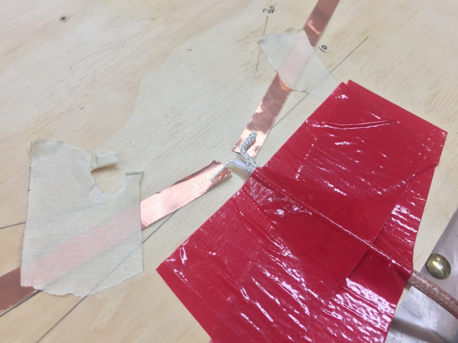
Cutting one of the two dipoles of the VOR/Localizer antenna to the proper length

Getting the geometry of the antenna fixed

Before soldering

Voilà! One VOR/LOC antenna completed.

These antennas are mounted with a 10º to 30º angle in order to negate the null reception zone at the tips. I used an angle as close to 30º as possible for the VOR/LOC antenna, but only 10º on the GS antenna since the Glide Slope station is always in front of the airplane during an approach.


Getting the antenna and cable run situated

I stole the toothpick trick from my builder buddy Wade

Glide Slope antenna finished

More toothpick action

To separate the shield from the inner wire, one might unbraid the shielding, or pull the inner core out through the shield.


I started by pushing the outer conductor back...

...and used a pick to open up a small window...

... then bent the cable...

...and helped myself again with the pick...

The inner core was out in no time

The baluns sole purpose is to keep reflected power from traveling down the outside of the coax braid and radiating or reflecting into the rest of the airplane’s electrical system along the way. Three of them are able to stop 99.99% of this energy, and like the wires they get buried into the foam, then microed over.


I picked this 0.25"x0.25" tool from the Dremel box

This foam is no match for any tool

Cable, baluns, and soldered ends were sunken into the foam.

Another look at the VOR/LOC installation

Here's the Glide Slope installation

GS antenna from above

I made my antennas exit the back to the canard about 3” left of centerline since the radios will be on the left side of the instrument panel.


A panoramic view of both antennas from above

Using dry-micro to cover the GS installation...

... as well as the VOR/LOC

Coax cables exiting the canard from the trailing edge

For the coax cables to exit the canard I took the unusual step of creating a "flox blob" through which they would exit. This way skinning the top of the canard would be easier, and I won’t have to cut holes in the fiberglass in order to thread the wires through while glassing. Think of it as a big flox corner with coax wires running through the middle of it.


Building up a structural cover for the coax

As seen from the leading edge

Flox blob sanded down to a nice transition

Fiberglass will make a structural bond here without the need to cut holes in the cloth

Next time I will glass the top of the canard, thus the main canard build will be over. Non structural tips will get added later on.


Tuesday, May 09, 2017

Ch 10 - Canard - Part 11

Top spar cap (16.5 hrs)

Filling the trough on the canard with as much UNI tape as possible but no more, is super important. Experimenting with UNI tape is the main reasons I took so long to get this job done.


Top canard contour gauge highlighting the spar-cap trough


Using too little UNI tape would make the canard weaker, while too much would create a troublesome step on an aerodynamically critical component. Also, since the trough depth changes with the distance from centerline, some sort of a layup schedule had to be predetermined.

So, this past month I took time to explore different ways of determining this schedule, from mapping the depths of the trough every 3”…


Using machinist gauge blocks to determine trough depths


… to testing the average thickness of a 10 layer UNI tape layup in a simulated trough…


Simulated spar-cap layup on scrap foam

10 layer spar-cap coupon


Measuring thickness every 0.5" (1.3 cm)

See how the contour gauge is lifted off the foam on the far right (leading edge) of this photo? Not good!

Based on my tests, it appears that the epoxy does not add any thickness to a properly squeegied layup.

Therefore, the best method to determine how many layers of UNI tape can fit in the trough at a particular distance from centerline, is to use actual UNI tape stacked as in a real layup, and add or remove layers based on whether the contour gauge fits on top of the canard, or not.


Determining how many layers of UNI tape can fit at this given location

Let's paraphrase the goal of this step once more... fill up the trough with however much UNI tape one can fit in it, and end up flush on top with the rest of the foam.

To make a long story sort, I ended up with 9 layers with the following schedule (yours might be slightly different):

  • layers 1, 2 & 3 - full span 108”
  • layer 4 - 84” to 96”
  • layer 5 - 66” to 84”
  • layer 6 - 42” to 66”
  • layer 7 - 18” to 42”
  • layers 8 & 9 - 12”

If you are wondering as to why the top spar-cap uses more layers than the bottom, it is because the bottom spar-cap has the best work environment for fiberglass, i.e. all the loads are applied in tension, while the top spar cap has to be slightly overbuilt to cope with the compression loads of the upward flexing canard.

After cutting the UNI tape, I prepped the trough by lightly sanding it.


Scuffing up the surface before fiberglassing


Then I mixed some epoxy, wetted the trough…


Pure epoxy painted to the top of the shear-web (trough-bottom)


… and begun laying up the UNI tape.


Layer #1 (cross-strands were removed after this photo was taken)

Fibers must be straight for proper strength to develop

EZ-Poxy has the nostalgic brown look of yesteryears

Layer #2 being applied

Closeup of the UNI tape. The cross-strands are removed before adding epoxy.

Layer #3

Squeeging extra epoxy out at the far end

Photo taken after combing the fibers straight

Layer #4

Layer #5

Layer #6

Layer #7

Layer #8

Layer #9

Completed spar-cap


With the layup completed, I peel-plied the whole thing and went to bed. 


Peel-ply added

The next morning the “cleanup from hell” began. 


Cleaning up this mess took me a day and a half!


Cleanup took twice as long as the actual fiberglassing. 

Note to self: Next time around remove the duct-tape before the epoxy cures.

Doh!