Disclaimer

This blog is for entertainment purposes only, and is not meant to teach you how to build anything. The author is not responsible for any accident, injury, or loss that occurs as a result of reading this blog. Read this blog at your own risk.

Sunday, October 25, 2015

Center-section spar - part 6

Step 4 at last! (16.4 hours)

Warning: What you are about to see is not exactly as laid out in the plans. If you’d like to know my reasons for changing the layup schedule (slightly), read my previous blog entry. Your life depends on following the plans only, not copying what I am doing here.

I started Step 4 on the right side of the spar (left in the jig) by mixing up some micro slurry and coating the spar inner surfaces. I stopped the slurry treatment before reaching the inner attachment point area, this way I didn’t commit to doing anymore fiberglassing than I had to on day one. 

Since I still wasn’t sure how long would take to do the first section, I planned for one section a day, maybe two, to finish all four areas of the inner spar.


Keeping out of the busy inner bulkhead area

Next, I prepared a plastic bag with some micro, and used it as a pastry bag to create a fillet in all corners.


Micro pastry bag ready to go

A nice micro fillet in all corners

Close up of the bulkhead fillet

Working solo can be a real pain sometimes, especially when handling the large plies of BID of layup #2. I used a bunch of pins to help me hold it where I laid it.


Pins holding up the BID

The bulkhead section could not be straightened out, so I sliced it and overlapped it.

Wetting the glass using the shortened paintbrush worked well, but it took sometime to get the glass straight, and all the air bubbles out, especially at the far end where the glass bunched up like crazy. After trying unsuccessfully to make a round peg fit into a square hole, I ended up slicing it vertically and overlapping the two ends on the bulkhead.


The first section of layup 2 is completed

I'll be working on this end now


With the fist quarter of layup #2 done, I moved on to layup #4, where BID and UNI get together. This turned out being easier to do than to talk about it.


This is the way the next BID ply will have to fold

The BID is in!


I decided to pre-preg the UNI, then lay it in place.


UNI pre-preg

Showing the way the UNI will lay

UNI plies over the BID


The LWA1 aluminum plates had to be floxed with the rounded edge down, and facing the spar corner. I drew arrows on them ahead time in order to avoid confusion, and was careful to make sure their distances from the edge was 0.75” (1.9 cm) per LPC #28.


The inner metal attachment points get floxed. The pins hold the tabs in the proper position momentarily.


One last small layer of BID covered the tabs.


A layer of BID went over the metal tabs


That went pretty fast I thought, until I looked at the clock and found out 4 hours had already gone by.


This first section was completed in about 4 hours


Feeling pretty good, I decided to do another section before  quitting for the day.


Slurrying the second section
Adding the fillet in the corners

BID layup 2 covering the second section

Inner bulkhead and fillet added. Note layup #2 generous overlap area.

Other side of CS7 inner bulkhead

Demoing the BID layup on CS7...

... and the UNI stack.

BID and UNI in place

One more layer of BID on the outer side of CS7

Setting LWA1

LWA1 25" from centerline

LWA1 distance from CS7 set to 1"

Plastic sheet pieces set over the metal tabs

Device holding 10 lbs (5+5) bearing down on the outer tabs...

... and 10 more on the inner tab and a squeegee.

20 lbs (9 kg) spread over 3 tabs and a squeegee (5 lbs each)


Looking at the clock now, I had been working for eight hours non stop, and my lower back was starting to feel it. Oddly enough though, the most discomfort concentrated in my shoulders, no doubt due to the spar sitting high on the table. Oh well, I peel-plied the transition, and went to bed.

I began the next morning by trimming the glass, removing the peel-ply, and doing some light sanding in a few spots. 

Overall things looked good.


Sanding down the sharp hedges

Outer bulkhead CS8 detail

CS8 as seen by CS7


Since day one had worked so well, I repeated the same exact sequence of events on day two.


Day two took 8 more hours of non stop work. There was just no way I could have done Step 4 in one day by myself. I turned the shop’s heater up to 80℉ (27℃), and went to bed hurting in places I didn’t remember having.

After a good night sleep, I woke up and I once again trimmed glass, removed peel-ply, and sanded a few spots, then Step 4 was finally done!


Sunday, October 18, 2015

Center section spar - part 5

Changing the layup schedule of Step 4 (slightly)

What I outline here are my reason for doing something different than the plans. I do not imply or suggest that anyone do the same. Your life depends on following the plans, not on what I chose to do with my plane.

Make no mistakes about it, the plans specifically states Step 4 should be done as one layup. 

However… I will try to rationalize this away.

In case you haven’t noticed, Step 4 is a pretty big job, and having a few assistants would allow it to go more smoothly, and take less time.

Having only occasionally been able to work with helpers, mostly due to my weird schedule, and the local scarcity of such creatures, I knew going into this that I could not do it all in one take. Although I was concerned about it, the reality of my situation had me question this requirement.

You see, this is a very important structural layup, and I have no skills to second guess the designer. Still, I couldn’t help thinking that the statement in question seemed very generic and slightly out of context, and contained no explanations of why it extended its veil of authority over the entire inner structure. Maybe it could have been a little more specific as to which part really needed to be done at once, and which ones perhaps didn’t.

Clearly the thick and convoluted layups #3 and #4 needed to be done at the same time, since they created the base for the aluminum attach points. The better chemical bond of an “all at once” layup might be more advantageous here, but the reasons that requirement extended to the entirety of layup #2 eluded me.

After all layup #2 is just a single ply of BID covering the whole inner surface of the spar, and overlaps itself many times due to the relative small size of the BID roll, compared to the spar it has to cover. 

Since when had a single BID layup become so critical that had to be done all at the same time?

Perhaps the wording sequence of Step 4 had been slightly unfortunate, and maybe a more creative interpretation would have allowed for an improved building cycle for the unassisted builder, while at the same time not giving up the required extra strength of the “all at once” construction.

After much pondering, I came up with an alternate layup schedule that would allow me to perform this step in 2, to as much as 4, separate glassing sessions, apparently without sacrificing strength.

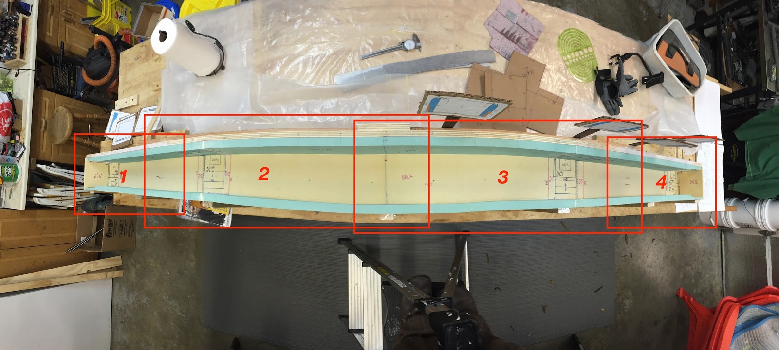
My idea was to subdivide layup #2 in such a way to make sure that the unavoidable BID overlaps would always occur outside of the main layups #3 and #4.
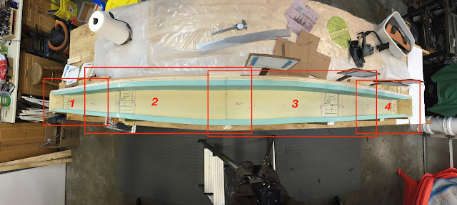

4 separate BID sections making up my layup #2 (each number represent a possible separate working day).

The peel-plied overlaps occur away from any major layups under the metal attach points (LWA1)

Using this new schedule, the fiberglassing of each hard point would still be “laid as one” on a fresh layup #2, but these could happen on as many as 4 separate days. 

The departure from the plans would only be in the manner in which the single BID (layup #2) covering the whole interior, overlapped itself to make up a single BID sheet. Because single BID plies are relatively weak structures to begin with, I saw no point to the requirement that these overlaps be done all at the same time.

While I could not find anything wrong with this approach, I decided to ask around. 

Lacking the engineering skills, and since other builders liked my idea, I turned to a very conservative, well known Aeronautical Engineer that specializes in composite structures. He has build these planes, and is very well regarded in the canard circles, but shall remained unnamed since I didn’t ask for his permission to publish his name and comments. He also liked my idea, and described the single BID ply as perhaps a way to “stabilize the foam”.

Happy with the outcome of my consultation, I modified the schedule for my Center-Section spar. My new plan would be to start at one end, and go as far as possible, then peel-ply the BID transition, and pick it up again another day. I reckoned I might be able to do 2 quarter sections per day, and be done in two days, depending on how much time this really took, while retaining the ability to split it up into up to four days, if I needed to.

Next time it will be “fiberglassing time”.


Sunday, October 11, 2015

Center section spar - part 4

Prepping for Step 4 (6.5 hrs)

Since fiberglassing the inside of the spar was going to be a big job, I decided to get as much prepared ahead of time as possible, and while it was still fairly easy to do, I also marked all Butt Lines (BL) on the center-section spar, for future reference.


Marking Butt lines every 5" (12.7 cm)

BL 35

BL 55

Next came the 6 aluminum plates (LWA1) that would be bonded to the inside of the spar. The easiest way to cut these 2” (5 cm) wide tabs is to buy a 2” wide strip of aluminum then cut as needed, so that’s what I did.


Marking the aluminum tabs for cutting

Six tabs are required inside the spar

One requirement for these tabs is to have one corner rounded to a radius of 0.100” (2.5 mm). Since I butchered my first attempt at sanding such radius on the first tab, and sanded part of my my gloves, I decided to leverage technology in order to make the job easier, and to preserve my digits.


Cutting the LWA1 radius with a CNC mill


The result speaks for itself…


That is exactly a 0.100" radius

Over and over and over...

With the radius situation under control, I scuffed all the tabs, and Alodined them.


A bit Neandertal after the previous CNC operation

This Alodine is a bit weak

Alodine is pretty expensive, and degrades quickly over time. My one year old Alodine required 15 minutes for a thin covering, while 1 to 2 minutes was normal when new.

Anyway, next item on the list was to make the interior bulkheads CS6 and CS7.


Finding a scrap piece of foam that fit

Here's a brand new bulkhead

Finally, I cut all the fiberglass I would be needing.


Scraps of cardboard taped together to make a fiberglass cutting template

BID getting marked at 45˚

BID for layup #2 getting cut


Cutting the BID for layups #3 and #4

Testing the BID of layup #4

Testing the BID of layup #3

Cutting the UNI for layups #3 and #4

Testing the UNI of layup #3

Testing the UNI of layup #4

All fiberglass and bulkheads sealed in ziplock bags awaiting "the day".

CS7 inner bulkhead and fiberglass in a ziplock bag

CS6 inner bulkhead and fiberglass in a ziplock bag

Fiberglass for the outer bulkhead CS5 in a ziplock bag

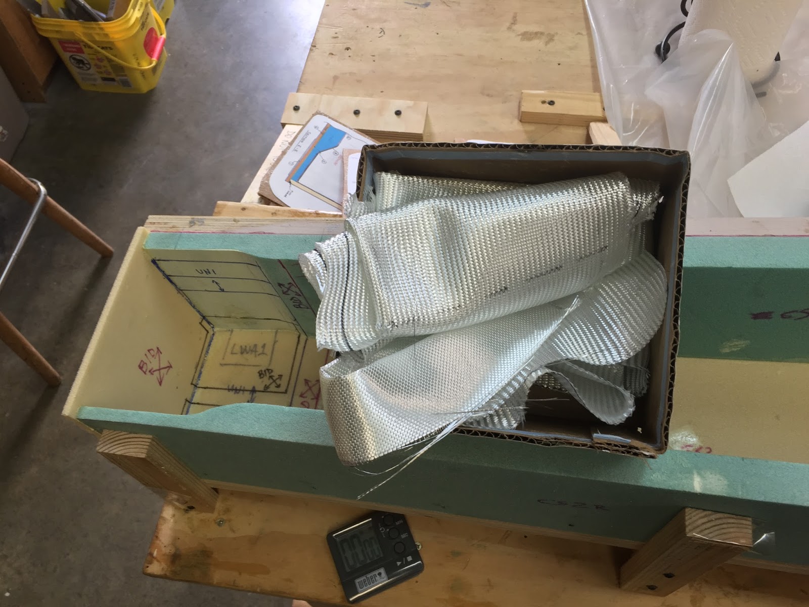
Fiberglass for the outer bulkhead CS8 in a box (I ran out of ziplock bags)

The plans require the use of a 5 lbs (2.3 kg) weight over each tab during cure. However, because of the slant in the spar, the weights tend to slide off the tabs. 

One excellent tip I received from BizMan was to fashion some kind of device ahead of time, in order to keep the weights from moving.

Introducing the EZ-Puppy…


Leveling the legs

This system actually worked great

Being a four legged animal adept at carrying weight, it should have perhaps been named the EZ-Mule.

One last small tip I picked up from Valerie Harris from EZ-Jets, was to cut the handle off the paintbrushes in order to reach inside the spar more easily.


That's how you know Valerie has done this many times

I would grow to appreciate her advice over the next couple of  days.