Disclaimer

This blog is for entertainment purposes only, and is not meant to teach you how to build anything. The author is not responsible for any accident, injury, or loss that occurs as a result of reading this blog. Read this blog at your own risk.

Wednesday, September 09, 2015

Center section spar - part 2

The foam structure (23.8 hrs)

Having banned Urethane foam from any important structure of my plane, let me introduce you to “le foam du jour”… a combination of ¼” (6.3 mm) PVC, and 1” (2.5 cm) Divinycell.


All the foam needed to build the main spar


Step number one consisted of making the parts I would be needing, by reproducing the plans’ measurements onto the foam, then cutting the blanks out.


Drawing the vertical sections of the spar on the thin foam

Top and bottom pieces of the spar are made of the much thicker 1" (2.5 cm) foam


I used the table saw for the thick foam, and a razor knife for the thin stuff.


A simple razor cuts this foam easily in one step...

...while a table saw helps immensely with this much cutting to do, and all cuts are straight, vertical, and identical in minutes.

Before whipping out the micro, I applied clear tape on the jig anywhere a foam to foam joint would occur. This is standard procedure to avoid gluing the foam to the jig.


Tape as needed, even better tape it all. I missed one spot in the middle that ended up causing me some trouble later.


In order to comply with the jig’s master measurements, I sanded the foam in place on the jig, then finally got to play with the smelly stuff.


Actually this West System epoxy doesn't smell at all, and dries fast (occasionally even too fast)

All rear foam pieces (bottom on the jig) glued together


While the micro cured, I went to work on the blue foam that will become the top and bottom of the spar once it comes out of the jig (remember that the spar is flipped up 90˚ while in the jig).


A little freehand cutting was required


The ends of the top foam pieces required to be carved down to a thickness of 0.7” (1.8 cm), while the bottom ones had to be brought all the way down to 0.4” (1 cm). 


From the plans (color added)

This used to be an easy, albeit messy process with Urethane foam, but Divinycell is much tougher, so I opted for the router.


The ends of these top pieces needed to be brought down to 0.7" (1.8 cm)...

... while the bottom ones all the way to 0.4" (1 cm)

I am no good with the router

Unfortunately, since I hardly ever use this treacherous tool, every time I do I always make the same mistakes, and by the time I figure them out the part is done, usually wrong, and in need of some fixing.

This time was like any other, and after going too deep, butchering the foam here and there, I had to go back and fix it with micro. Of course this process took way longer than if I had done it right the first time.


Crap!

What happened there?!

Since the rest of them didn't turn out any better, the micro had to save the day.

A few hours later, I was back in business.


At least this time around I was able to control the dimensions much more accurately than before by sanding gently, repeatedly, and taking lots of measurements, so in the end it wasn't too bad.

Next, I made myself a tool with which to sand the blue foam flush with the jig’s back piece, a process that would have to be repeated for all the blue foam pieces.


Another attempt at making life easier

This worked great... in theory

I suppose it worked okay, but it wasn’t as good as I had hoped for, and still required a little freehand sanding afterward.


Using a regular sand blockwould have probably been faster

One other step that took more time than I had imagined turned out to be trying to keep the bottom blue foam (forward in the jig) perfectly vertical. 

You see, while the top piece (rear in the jig) benefits from leaning against the vertical plywood, the bottom piece has no such help in place. Furthermore, this foam has to make a 1.8˚ rearward bend (as seen from above the jig) at ± 9” (22.9 cm) from the centerline, but the tough Divinycell does not change direction well.

I used some of the wood that Aircraft Spruce packs its foam with, and some random steel plates as makeshift vertical members on which to rest the bottom blue foam (forward in the jig) while the micro cured.


Shimming the wood to vertical

Spar top (rear blue foam in the jig) getting microed to the spar back (bottom in the jig)

Spar bottom (forward in the jig) getting microed as well. 

Nails added to prevent the foam from sliding on the micro

Every clamp I own got used

Left end (right in the jig) detail of the spar

Making sure the foam remained vertical 
Attaching the last bottom piece of the spar (forward in the jig)

Last piece microed and nailed to the rear foam (bottom in the jig)

Left end piece (right in the jig) microed and nailed

While I waited for the micro to dry up, I used Photoshop to add colors to the drawings in chapter 14, and modify them per Long EZ plan change #99, published in Canard Pusher #32, which says "The UND layup #3 & #4 are incorrectly shown to lap onto the CS7 & CS8 bulkheads. The words describing this layup on page 14-2 are correct. Layup #3 & #4 are laid up onto CS2 & CS3 in Sections E-E & F-F and only onto CS1 in Sections G-G & H-H."

After printing the new and improved drawings, I glued them to a piece of cardboard from the same box the foam shipped in. Next, I cut them out, and stapled them to plastic shims.


Cross sections edited drawings glued to a cardboard

Stapling the drawings to plastic shims

Putting each cross section drawing in the exact spot and orientation where it belonged on the spar, helped to make sense of the complex set of layups to come.


Drawings placed in their proper locations

This helped me understand what would be going on at any location

Staggered cross sections

You can get a real sense of how the spar changes going front to back (up to down in the jig)


Once the micro dried up I attached the last piece, the right end cap (left in the jig).


Before the night was over, I decided to get a little more work done, and glassed the inside surface of the forward three panels (top in the jig) of the spar on the worktable.


The center pieces had to be glued together

Applying micro slurry to the foam

One ply of BID at 45˚ over the center piece

All forward pieces (top in the jig) glassed

These panels will be attached to the rest of the spar assembly after the inside portion of the spar gets glassed.


Spar front pieces

Checking the dimensions


Wednesday, September 02, 2015

Center section spar - part 1

The jig (15.5 hrs)

Welcome to chapter 14.

This is a very important chapter, because I will be building the center section spar, the real backbone of the airplane. Most of the important parts of the plane like wings, fuselage, and engine connect here, so it is paramount that it is built correctly.

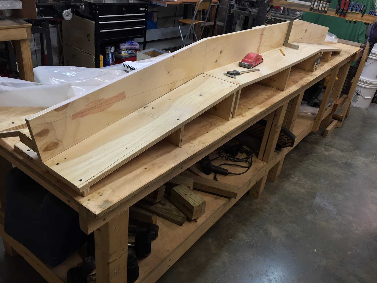
The wing spar is basically a rectangular box with swept ends, and it is initially assembled facing upward in a wooden jig. Get the jig wrong, and your spar will be just as wrong, so it behooved me to invest as much time and effort as necessary in doing it right.


The main spar jig (link to the 3D interactive jig)


One of the clues to how important this jig is can be gleamed by the dimensions specified in the drawings. All dimensions are given to the hundredth of an inch!


Measure with a caliper, cut with a table saw!

I am no carpenter, but I’d be willing to bet that not a lot of carpenters make pieces of furniture to that kind of accuracy. Nevertheless this is our path forward, so I’ll be striving to be as accurate as possible.

Normally, I would have gone to the store and bought some cheap plywood to erect this temporary structure, however I still had some suitable scraps of cabinet-grade plywood around the shop, leftovers from building the heated epoxy box and the fiberglass cutting table. These had been sitting around for 4 years awaiting some good use, and they were already paid for, so they were called for duty. They will be suitably reused in other parts of the project when this jig is no longer needed.

The only issue with this plywood was that it wasn't 100% straight (more like 95%), but I decided to use it anyway, and to take care of it during the assembly.

Task #1 was to recreate the exact measures from the drawing onto the wood, cut it as close as possible to the lines, then sand where necessary.


Following the pencil line with the right edge of the fat part of the saw blade's teeth. Yikes!

Manning the table saw


It helps to have a lovely assistant for tasks such as these…


Thank goodness for the help

To avoid having to draw and cut everything twice, I doubled up the plywood, screwed the two pieces together, and cut along the lines with the help of a straight edge.


Two boards screwed together

Same two boards after a couple of cuts

This method was not as precise as I had hoped, and left a 0.047” (1.2 mm) saddle, that I later filled with Bondo, and sanded to flatness heaven.


This edge will be used to shape the foam to size, so it needed to be repaired.


To help hold the vertical back piece D (I actually used two half pieces for this) perpendicular to the table, I bought some 90 degree steel bracket. 


Bomb proofing the jig


They turned out to be a bit off right out of the box, but after a good beating they changed their minds and decided to get on with the program.


This might be good enough for a bookshelf

There we go, all better now!


Before erecting part D, I attached the two halves together on the table, with the help of a straight edge.


Attaching the two D halves

Joint closeup


While I was at it, I screwed 2x4s on its back to ensure it would remain straight once vertical.


More recycled lumber in use, the long piece is from "The straight tower of Pisa", the short 2x4s are from the fuselage rotisserie 

That's what I'm talking about!


Next, I cut and assembled the remaining pieces of the shelf (A, B and C), and the supports (E,F, and G) that went under them, then performed the Bondo magic trick.


The jig and its components

Adding Bondo to level the shallow saddle

Sanding the Bondo flat

The completed jig


Everything got screwed to the tabletop, with enough screws to be able to withstand a nuclear blast.


This jig not going anywhere!


I had to do some minor tweaking at the very ends, where the plywood was ever so slightly out of square, but it was pretty easy to do, and it was all brought back to resemble a cartesian dreamscape.


Minor adjustment

Both ends needed a tiny help