Nose bumper (12.2 hrs)
The Long EZ is certainly one very unconventional airplane, so much so in fact that the uninitiated often mistake which end is the front, and which is the back.
And how could one blame them! The Long parks with the nose resting on the ground (after retracting the front wheel), engine aiming to the heavens, while the canard could easily pass for tail feathers. One should be excused for thinking it is a taildragger, except when he notices that the seats are facing the “wrong” direction.
Talk about a conversation starter. You’ve got love Burt Rutan.
About the "nose on the ground" thing… something needed to be done about that. The plans' solution was to cut “a thick piece of rubber from an old truck tire” and attach it to the bottom of the nose with a fiberglass flange.
I suppose that would have worked just fine, but over the years I’ve seen plenty of more elegant solutions gracing the noses of many a Long EZ so, once again I decided to venture out on my own, designing a new bumper from scratch, and machining it on the CNC mill (if milling rubber was even possible).
I had two antithetic objectives in mind, on one hand I needed to make sure the design would be as aerodynamic as possible, on the other I needed to maximize its size in order to have enough surface to support the weight of the nose. Searching the internet for suitable profiles, I settled on a NACA 0050, for no other reason than it was fairly wide, symmetrical, and aerodynamic by design.
I ran a computer program that calculated two-hundred coordinates for the profile, and multiplied the results by a factor of 2.5. This way I could reproduce the chosen form within the lateral confines of a 3” (7.6 cm) hockey puck.
The hockey puck idea is not new, as a matter of fact it is pretty common in Long EZ circles, but I wanted mine to be a proven aerodynamic design, and I wanted it to be easily removed and replaced, in case it wore out or I dreamed up a different design later on.
Importing the 200 coordinates in a CAD program was easy, then I spent some time figuring out how to make it removable, and here’s what I came up with…
 |
| The flared sides increase the surface in contact with the nose, and theoretically also reduce interference drag. |
 |
| The actual rubber is smoother than the one these renderings depict |
To withstand the side loads of the profiling operation without moving, the puck had to be bolted down firmly, and this required drilling it, then counterboring the top holes. But holding the puck down with traditional clamps deformed it enough that the hole coordinates could no longer be assured.
To bypass this problem, I designed an aluminum fixture with a depression in it the same shape as the puck, but 0.003" (0.076 mm) smaller, that would hold the puck in a friction lock. This design would enable precision drilling and counterboring operations without deforming its shape, or allowing it to rotate in the fixture. After these initial steps, I could quickly, and reliably remove the puck and bolt it down for the profiling operations.
The fixture saved a tremendous amount of time that would have been spent setting up the clamps, and finding the puck's machine coordinates (multiplied by the number of pucks I decided to make). Gone was also the danger of a collision between cutting tools and clamps.
 |
| Aluminum fixture with puck and bumper |
Machining rubber proved to be a bit of a challenge with a straight end-mill. Sharpness of the cutting tool was paramount, but even a brand new one left quite a mess in its wake.
 |
| I swear there is a partially made bumper in there... somewhere. |
 |
| Had it not been for the sharp cutting ball-nose end-mill, this project would have been a bust. |
Freezing the rubber in liquid nitrogen would have been helpful, but I had no such setup available. Luckily for me the ball-nose end-mill used for the finishing operation left a nearly flawless surface.
 |
| A little dusty, but 100% done. |
 |
| Besides a lot of vacuuming, no further operations were necessary. |
 |
| Before and after profiling |
Making the bumper
The anchor plate to be embedded in the nose of the plane would need to be precisely made if the bolts were to engage the anchor's threads without distorting the bumper. I chose a spacing of 1.200” (3.05 cm) between holes.
I made the anchor out of a leftover piece of ⅛" (3.2 mm) thick aluminum bar, the same one I used for the nose gear doors.
First, I measured the exact thickness of the bar and the K1000-4 nut-plates. They came in at 0.126” (3.2 mm) and 0.042” (1.067 mm). I then put these values into the “Rivet chooser” Excel spreadsheet I made (available in the Downloads section of this blog). This gave me the dimensions I needed.
 |
| This spreadsheet has saved a lot of braincells from an untimely end |
Using the “recommended hole edge distance” of 0.234” (5.94 mm), I scribed the outlines where the rivets should go.
 |
| Scribing the lines for the recommended hole edge distance |
Lining up one of the nut-plate’s holes with the crosshair, I center-punched that and a second one 1.200” further down.
 |
| Bottom hole positions |
Next, I drilled both holes with the #40 (2.49 mm) drill, as suggested by the spreadsheet, and inserted the rivets the spreadsheet chose automatically based on the thickness of the materials.
 |
| Holes drilled, and chamfered. Rivets acting as hinges to locate the top holes. |
Because the scribed lines were parallel to each other, all I needed to do was to drill the two top holes on the line using the nut-plates as guides, to ensure the main holes of the nut-plates would end up exactly 1.200” apart.
 |
| Top holes identified |
The entire process was quick, and worked flawlessly.
 |
| Test fitting the bumper with the anchor |
The next challenge was to mount the anchor to the nose, below the fiberglass skin. Page A6 shows the bumper directly below the main nose round bulkhead (NG31).
 |
| No explanation for this location is given (perhaps location isn't critical) |
Given the need to excavate foam and fiberglass in an area with very thin cross-section, I was able to only partially straddle the bulkhead with my anchor point.
 |
Marking the cut lines
|
 |
Cutting carefully
|
 |
Separating glass from foam is not as easy as it looks
|
 |
Removing bulkhead foam
|
 |
Testing the fit
|
 |
| Foam and micro was removed below the edges of the remaining fiberglass |
I decided to add some strength a bit later, by adding 5 plies of staggered BID to help spread the weight of the nose over a wider area culminating in the rubber bumper.
Meanwhile, I had to flox the anchor in.
 |
| Keeping the anchor top surface flush with the fiberglass |
 |
| Hot-glueing threads to prevent flox from sticking to the bolts (it worked beautifully) |
 |
| Anchor floxed |
 |
| Flox dried and surface cleaned up |
After sanding the glass dull, I applied the 5 plies of BID, and peel-plied over it. Unfortunately, I forgot to take a picture of the layup until after the peel-ply was laid.
 |
| Scuffing the fiberglass dull |
 |
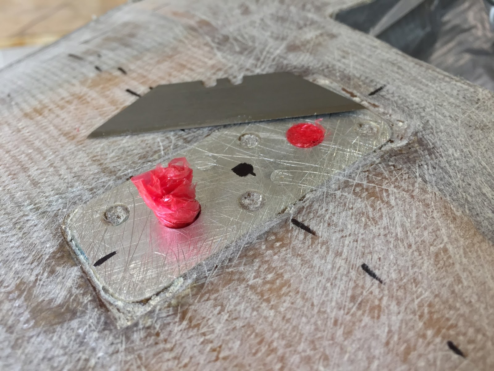
| Using Saran Wrap to protect the threads from epoxy |
 |
| 5 staggered layers of BID covered in peel-ply |
 |
| Highlighting the location of the 5 BID plies with the peel-ply removed |
The last step was to open up the holes over the anchor, remove the Saran wrap, and install the bumper for the last time.
 |
| Saran wrap removed from bolt holes |
 |
| Bumper finally bolted down |
 |
| Bumper in its final position |
 |
| Looking back |
 |
| A wider perpective |