Disclaimer

This blog is for entertainment purposes only, and is not meant to teach you how to build anything. The author is not responsible for any accident, injury, or loss that occurs as a result of reading this blog. Read this blog at your own risk.

Monday, December 15, 2014

CNC mill conversion - part 19

Redefining the term… ugly

In my last blog post I promised a final solution to the chips and cutting oil cleanup madness that accompanies every cutting job.

This weekend, I decided to do something about it.

As my first aluminum fabrication project I figured I’d do something totally not critical, like the CNC mill motors’ covers. They don’t need to be good looking (although it wouldn’t hurt), all they need to do is keep metal chips, and cutting fluid (perhaps flood coolant in the future) away from the electric motors, and their mechanical couplings. 

I purchased some ⅛" 6000 series aluminum angle at SpeedyMetals.com, and went to work.


Speedy Metals commercial


1¼"  x 1¼" (3.2 cm) extruded aluminum angle 6061-T6 


Unfortunately the aluminum angles came up short (apparently I can no longer add fractions), and the fit up left me with 1/4” gap. 

Well, it turned out I just forgot to consider the material ⅛" thickness, twice! 

Crap!

When 1¼ plus 1¼ does not equal 2½ 


With my clever plan in shambles, I quickly improvised by ripping some 1/2” strips with the table saw, in order to close the gap. 

Improvising is bad!

Have I mentioned these covers don’t need to look good?


The next best thing to an open gap


Welding aluminum seems to be hit or miss for me, I get some good runs, but sometimes I dig some craters. I don’t blame the machine for this, I’m sure it is 100% operator induced.


Well, at least it was a good practice session.


After the top pieces were done, I ripped 2 skirts out of some more angle,  then tacked and welded them.


Tacking one skirt

Finally, a straight run!


After doing both sides like this, I cut off the rear top corner (the one closer to the operator), welded a flat piece over the gap, then ground the welds smooth so that the coolant could flow over the edge then down into an eventual basin.


Fit & Finish... 1 out of 2 ain't that bad


Next, I drilled and tapped four 8-32 holes in the brackets. 

Let me tell you… spiral flutes taps ARE the way to go, I actually used them with a drill later on. See how they pull the chips backward by design? No  need to go back and forth with these babies.


Spiral flute tap in action. These taps are the bomb!


With the four bolts in place the cover became A LOT sturdier than I had anticipated. There is absolutely no wiggle, and I can actually move the mill around by pushing on the cover (not that I would need to).


This might actually work


Yes I know, it is one of the ugliest things to come out of the EZ shop to date, but then again, it doesn’t really have to go anywhere. 

Focusing on the positive… one good attribute is that, even with this enclosure, I can still operate the mill by hand with the crank wheel, just in case.


I'm still able to operate the Y axis manually


Although lately I have actually removed the wheels for a smaller profile, and since it takes less than a minute to put them back on, I’ll just keep them off to reduce the number of times my stomach hits the Y axis crank.


Since I don't use the mill in manual mode that often, I chose to reduce its footprint.


When I get back home from this trip, I’ll make the cover for the X axis, which I’m sure will turn out just as ugly, but perhaps, and more importantly, just as functional. 


Monday, December 08, 2014

CNC mill conversion - part 18

Fixing some minor annoyances

The mini-mill CNC conversion has been one of the most difficult builds I have ever done, with plenty of obstacles along the way that I have had to overcome to get it to where it is right now. The learning curve has been truly exponential in many areas, with much more learning yet to be realized.

I’d like to think that the complete exposure to the bowls of the machine, the planning, creation, and modification of my own parts from scratch using sometimes inaccurate plans, and the level of attention to details required, have made me a more knowledgable and careful operator of this magical piece of equipment.

There have been however things that I have hastily put together or bypassed, for the purpose of moving the project along, and that needed to be addressed. This time I will focus on three minor annoyances.

As I have been cutting more and more metal, a few hot spots for chips and cutting fluid accumulation have been identified: 

#1 the completely exposed ways of the Z axis 
#2 the unprotected electrical connections of the motors
#3 the motor to ball-screw couplings, including the motors themselves

Again, these have been minor issues so far, but they create a lot of cleanup work on a regular basis, and also have the potential to affect the functioning of the mill, if they end up in the wrong place.

I decided to begin with the most cleanup-work generating issue, the lack of a barrier between the cutting tool and the Z axis ways.


Metal chips are flung in all directions, and like to stick to the lubed Z axis ways.


The X axis ways are naturally hidden, while the Y axis ways have two rubber chip guard bellows. So, why not the Z axis?

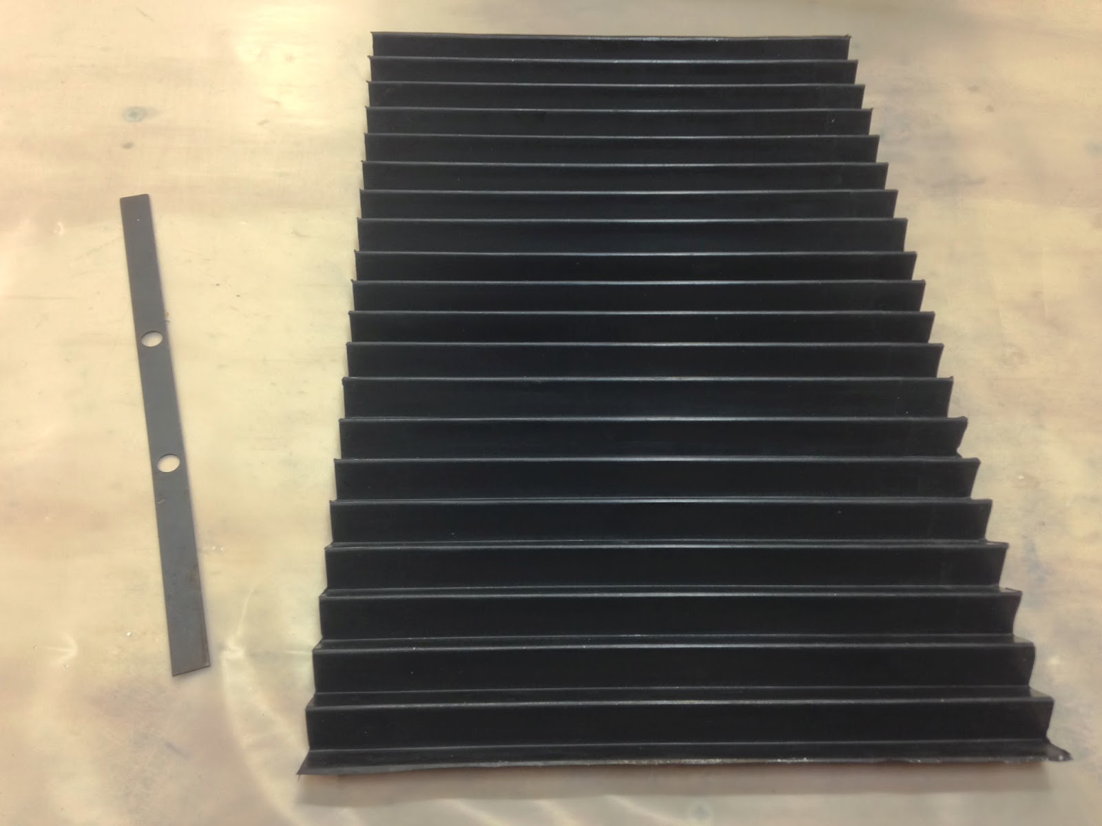
I ordered a new bellow and metal retainer from the LittleMachineShop.com, and began the alteration.


LittleMachineShop.com items #1474 and #1431


It involved drilling and tapping two holes into the lower flange of the mill’s head. The only difficulty here was getting the drill in position, since the spindle is in the way. I used a shaft extension to get around the spindle, and the tapping was done by hand the old fashioned way.


Tapping two holes in the mill's head. Note the bothersome spindle location.


Doubling up on the existing lower baffle attachment point, and installing the top one, I was done in just a few minutes.


Z axis protection in place


I might have to shorten the baffle by a few folds, time will tell. So far I think this is one of the quickest and easiest upgrades, and I will enjoy it with every machining operation to come.

Moving to issue #3, keeping the crud out of the motor coupling makes a lot of sense, especially when you have to get in there for maintenance. In the past I have relied on wide masking tape applied just before using the machine, but as I got lazier, I left it there to soak up all kinds of cutting oils, and cleaning fluids. It got pretty nasty.


Oil soaked tape protecting the Y axis coupling

Same nastiness on the X axis. By the way, the tape is usually covered in metal chips as well as cutting fluids.


Kicking the can down the road a bit, I decided to replace that tape with HVAC metal tape from Home Depot. I should get a little more milage out of it, until I finish working on a global solution that will completely enclose couplings and motors.


HVAC metal tape

That should work for a little while

I left the bottom is open for possible chip and/or coolant evacuation


The cover I have in mind will be fashioned out of aluminum angles welded together. Hopefully it won’t be as ugly as I picture it in my mind, and should be a pretty good opportunity to practice some more advanced AC welding skills.

The complete enclosure of the motors (at least 3 sides) will also make it possible to use flood coolant down the road, if I chose to do so.

Obviously flood coolant and chips are not very friendly to exposed electrical connections…


These were supposed to be temporary motor connections

Chips and cutting oil still clinging to the terminal blocks even after a good cleaning

Z motor connections are mostly out of harm's way


… and so I moved on to addressing issue #2 by waterproofing the connections.

I purchased three waterproof plugs kits (4 wires model) from McMaster-Carr, including the crimper tool and an extraction tool, and crimped away. 


McMaster delivery

Wire seals (4 included in my kit) slipped over the wires 

Socket (4 included in my kit) getting crimped on the wire

Socket crimped. Rear tangs closed slightly to hold the wire seals for secondary crimping.

Rear tangs in crimping tool

Rear tangs shaped over the wire seal

What it looks like after crimping

Four crimped sockets ready to be inserted in the plug

Sockets need just a small push to lock into the plug

Tab ready to close on the four sockets

Tab closed, sockets locked in place.

Business end of the waterproof plug


I also purchased an interference shielding sleeve, to reduce the chances of interferences at the motors. The cables from the controller box are already shielded. The sleeve has a grounding cable woven in to dissipate any charges to ground, but I chose to not connect it at this time.


Wrap-around interference shielding sleeve


One nice thing about this sleeve is that it is slotted, so inserting the wires is a piece of cake.


I used about 12" (30 cm) per motor

Y motor plugs connected

X motor plug getting the sleeve

X cables protected from possible electrical interference


The material the sleeve is made from seems like it would collect chips and oils, so I purchased some self-fusing high temperature tape, and wrapped the sleeves generously with it.


This tape is pretty cool

Forming a waterproof outer shell

Y motor cable sealing completed

X motor cables sealed


With two axes taken care of, I moved on to the Z axis.


Z motor cables were next

Sockets

Pins (4 included in my kit) crimped

Plug and sleeve added

Self-fusing tape used

Male and female plugs before mating (1 of each included in the kit)


The incremental improvements I have made to the mill have rendered it easier to clean now, and more durable, and that should make it even more fun to work with.


This little mill has come a long way