Chronicling my Long EZ construction (and a few other things).
Disclaimer
This blog is for entertainment purposes only, and is not meant to teach you how to build anything. The author is not responsible for any accident, injury, or loss that occurs as a result of reading this blog. Read this blog at your own risk.
I really like the brake/rudder pedal design I came up with, and although actual use might eventually dictate small modifications, for the time being the EZ shop R&D department (Research and Development)has been shut down, while the Manufacturing branch is ramping up production of the system's components.
To maximize leg room in the nose, I had planned on mounting the brake assemblies as close to the outer sidewalls as possible, which means they would be at a roughly 12˚ angle with the airplane centerline. I had also decided to remove the F22 stubs that were part of the original brake design.
While it looks bigger in the photo, the angle is barely 12˚.
One of the improvements I had considered, was to weld the top horizontal tube at a 12˚ angle to make it parallel to the bulkheads. This would prevent my feet from getting a little twisted while pressing the pedals.
After sitting in the plane for sometime though, it turned out that all of these changes were unnecessary. My left leg rested more naturally against the sidewall, and easily activated the brake pedal along the bracket centerline, this arrangement also eliminated any concerns of side loads being applied to the master cylinder piston. Furthermore, the little stubs felt pretty comfortable to rest the bottom of my heels against, marking the correct foot position for best brake activation. So, I decided to make no further changes, and leave everything as it was.
The brackets will bolt to plywood anchors. I am still using the same plywood piece I had purchased for the firewall a few years back.
Aviation grade plywood leftover from the firewall
These will become the anchor points for the brackets
A 45˚ chamfer was added to ease laying the fiberglass
3 holes were drilled
These plywood pieces will be floxed to the nose floor, then fiberglassed over. In order to have good attachment points for the bolts, I followed my friend Ary’s lead, and purchased some Tee nuts inserts for wood from McMaster-Carr.
Tee Nut
These worked very well, and were easy to install.
Tee nuts about to be installed.
Tee nuts installed with the help of a small hammer
The Tee nuts seem to hold very well
I couldn't resist putting the assembly together
I made two new flanges out of 0.100” (2.5mm) thick 4130 steel on the CNC mill.
Holes pre-drilled
Holes enlarged to final size, and engraving done.
Flange getting cut, one 0.007" (0.18mm) slice at a time.
The umbilical cord is coming off next
Here's the new born all cleaned up
A little lathe work was necessary to create the bullet-like nose of the master cylinder rod extensions.
Creating the rounded nose that will press on the flange
Drilling a hole for the set screw
The pedal vertical components were drilled, and cut on the mill.
While CNC was non strictly necessary here, it helped increase the consistency of the parts.
The slider piece had its three slots CNC cut as well.
These were fun to watch getting cut
Slider nearly finished, before final cutting.
Lastly, the rudder cable attachment point was made on the lathe.
Tapping the rudder cable attachment point for an AN-4 bolt
Rudder cable will connect here
There will be an adjustable piece connecting the top of the brake pedal to the actual rudder cable, but I will design it and machine it when I get back from Europe.
Unfortunately, I ran out of time before I could finish making all the parts, and I had to leave on another trip. So, there will still be a tiny bit of machining to be done next week, before the welding session begins, and I can turn all these parts into actual pedals.
Almost all the parts for the pedals are finished
I'm pretty happy with the quality and consistency of these parts
It will take a long welding session to turn all of this into pedals
One of the issues I had welding 0.100” (2.5mm) thick steel plates to 0.035” (0.89mm) steel tubing, is that the tube melted before the plate was ready to fuse. I was still able to weld them by directing the TIG torch, and the heat, mostly toward the plate. This however was not a great solution, and though successful, the welds turned out very ugly.
What I should have done was to preheat the parts before welding them, and this is exactly what I intend to do next week using a propane torch.
No soon had we finished machining the first short bracket, than Wade and I started beating the crap out of it with a rubber mallet!
Though silly, the abuse might well represent the one inflicted by boots stepping on it over the years, and highlighted the fact that the top rails and webbing needed to be made thicker. Actually, they should have been thicker already, but I had made a drawing mistake while reducing its dimensions in CAD from 12” (30 cm) to 9.5” (24 cm), and didn’t catch it until we had already machined the bracket.
Doh!
Because this had been Wade’s first foray into CNC, I decided I let him keep the bracket as a souvenir of his hard work. In turn, he promised to send me picture of the mangled bracket next to the unit he had purchased.
Short bracket after being struck with a rubber mallet multiple times, next to Wade's (any similarity between brackets is mere happenstance). Photo courtesy of Wade.
Meanwhile, I decided to do some load testing on the 12” bracket I still had in the EZ shop, and depending on the outcome, make additional changes.
Overload testing of the 12" bracket
Satisfied and encouraged by the latest testing results, I moved on to machining the first one incorporating a few improvements (mostly increased webbing thickness, and edge distances).
This beauty will end up in the nose of my plane shortly.
The chamfering came out just perfect
3 bolts will hold it down, and its position will be adjustable to plus or minus 1" (2.5 cm)
It will attach to nuts, secured to an aviation-grade plywood, itself floxed and glassed to the nose floor.
A commonmisconception about CNC is that you can just press the start button, then walk away from the machine, but that's not even remotely true, at least not at my level.
Not including the weeks spent designing it, and testing its geometry on the computer, this bracket took over 6 hours to produce (2 hours per side x 3).
What made the process so slow were the 6 repositioning moves necessary due to its size (compared to my mill)and shape, and the countless tool changes. Actual milling time added up to "only" 3 hours!
Time lapse bracket machining
Master cylinder attach point
Sadly, once installed it might never be seen again.
Here is the 9.5" bracket next to the 12" one (aka "the original").
"Shorty" right below "the original"
Note the thicker webbing. No part of it is now any thinner than 0.200" (5 mm).
Sturdier and even lighter new design
Looks and strength, what else can a bracket hope for?
My friend and fellow Long EZ builder Wade, came over to visit me this past weekend, and caught me right in the middle of machining the shorter version of the brake pedal bracket.
Left side of bracket machined out of a 1 ¼" (3.2 cm) U channel aluminum extrusion
Since he had expressed an interest in CNC machining in the past, and the mill was not operational the last time he stopped by, I decided to seize the opportunity to bring him up to speed with a little "CNC boot camp".
I showed him the basics of CAD, CAM, Mach3, and G-code then gave him some hands on time on the CNC mill.
Wade changing the cutting bit in the spindle
He’s such a quick learner, and did a fantastic job, so much so in-fact that he ended up machining the whole center section of the bracket on his own.
First half of the center section completed, Wade is about to machine the far half.
I think he really enjoyed creating with metal in such a precise fashion, and the next day the little seed I planted showed signs of germination when he started inquiring about CNC machines, prices, etc.
New 9.5" bracket vs the older 12" one
I mostly gave him the same advice I gave Phil from the west coast, don’t do as I did. Buy a more capable machine from the get-go, then add a pre-made CNC kit.
I am coaching Phil right now in setting up his own hobby CNC shop.
Phil, a former Boeing 737 Captain that now manufactures high fidelity flight simulators, took my advice and returned his new Harbor Freight mill, purchased a much better quality Little Machine Shop one, and will end up modifying it with a CNCfusion kit later on. That’s the way I’d do it, short of getting a Vertical Machining Center already made.
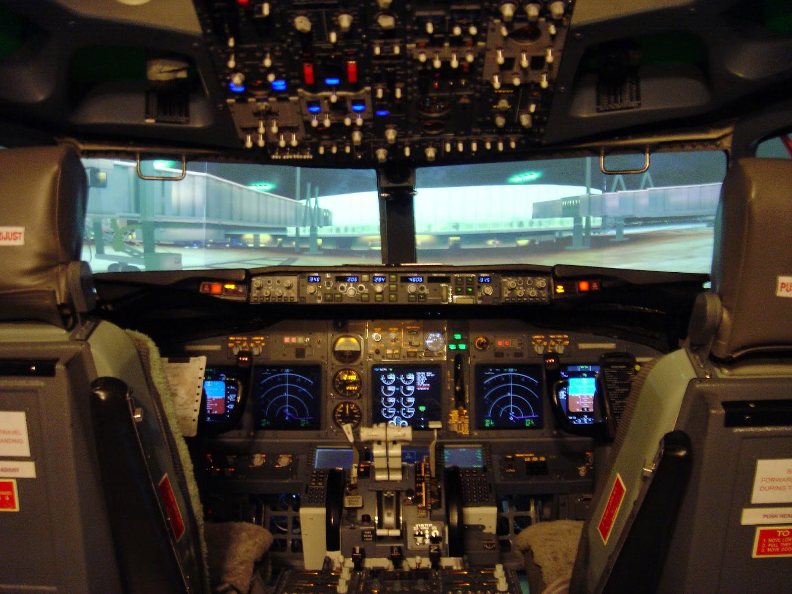
Phil's handy work, a fully functional Boeing 737 simulator (with visuals)... amazing! "I want to fly it!"
The new bracket came out really well, and the smaller size of the track will allow for more flexibility in mounting it in the confined spaces of the Long EZ's nose.
The shorter bracket makes it an easier fit in the nose
The geometry of the pedal assembly also worked great in all the positions for which I had drilled holes in the flange. Which position I will choose will have to be determined by sitting in the fuselage, and playing with it a bit.
Pedal fully aft in the middle hole position
Pedal fully aft in the bottom hole position
Pedal fully aft in the top hole position
Adjustability was a major driving factor in my design, and I think I will have plenty of it in the form of track holes selection (5 positions to choose from), flange hole selection (5 options there), and rotation of the piston rod extension (fine adjustment with at least 5 or more usable options).
That’s at least 125 combinations to choose from! Even a picky guy like me ought to find more than one suitable position.
The original brake pedals are pretty ingenious, they are light, sturdy, and as small as the designer dared making them. Better yet, I own a set of never-before-used ones already. The left one was a gift from my friend Walter, and it’s an original Brock specimen (1980’s vintage), the right one I threw together on a “slow day” using 4130 steel from my leftover pile.
Old and new together
I can only imagine improving a couple of things. First, I’d like the pedals to be a tad bigger so that I can steel feel them through winter shoes, and second, I’d like to do away with the cross-tubes, this is just a nuisance to have to get over every time I’d like to stretch my legs in flight, and a newly designed pedal set could easily eliminate them.
Initial brake assembly idea
These issues alone wouldn’t justify “reinventing the wheel”, but the availability of CNC tipped the balance in favor of more R&D (research and development), and so it was that I started down another rabbit hole.
My original intention was to use a 3/4” (1.9 cm) U channel. This forced me to carve a lot of relief around the master cylinder base, or it wouldn’t be able to swing properly.
A lot of aluminum was trimmed to remove the interference
Close up of the critical joint
Later, when I tried to purchase a 3/4” U channel, I found that nobody carried it, so had to settle on a 1-1/4” (3.2 cm) wide extrusion. This negated the requirement for the relief, since the body of the master cylinder now easily fits within the channel.
However, I didn't want to design a new bracket since I actually liked its curvy profile, and I rationalized that it would be lighter to boost. So, since I was going to have to machine it anyway, I decided to make it even lighter (read: fancier) by incorporating a few lightening holes.
Why not!
The biggest problem I faced was the length of the bracket. It was just too big for my little mill, so I decided to split the work in two zones, the “brake pedal” half, and the “master cylinder” half.
A small reference hole in the middle of the bracket would tie the two zones together. Because this hole would be the only mean to zero out the mill’s coordinates after repositioning the U channel in the vise, it would be one of the first features to get machined.
This arrangement worked fairly well, given that precision was only needed for looks, rather than fit.
First half done. Getting ready to machine the second half.
finished bracket
Spacer had to be machined on the lathe because of the wider U channel
Inch reference marks
This is how it was done
With all the cool stuff starting to come out of the garage, I thought it would be appropriate to give it a name.
I decided to call it the “EZ shop”.
What do you think?
Anyway... I decided that machining aluminum brake pedals would be too difficult for me at this stage, and that I would start out with welded steel ones, perhaps swapping them in the future.
I started out with 2 different 4130 steel tubes, the big one would become the pedal, while the smaller and thicker tube would become the hinge point, and get welded to the former.
4130 chromoly steel tubing ready to become a brake pedal
I started working on the hinge by precision cutting the small tube on the lathe, and fitting it to the bracket.
Pedal hinge
Next, I drilled a hole in the big tube the same size as the small one.
Creating the mating hole
The two got welded together, then the assembly went back on the mill for some more drilling on the opposite end. This time I enlarged the hole until the tube was severed, leaving the perfect notch to fit the part that my foot will actually stomp on.
Tubes mated and welded together (left), and top of pedal getting prepared (right)
A drill with the same diameter as the tube cut it in two
Tube welded to pedal hinge
I crosshatched a pattern with the lathe on one end, then welded it in the shape of a capital T.
Top tube crosshatched and welded
A view of the whole assembly
The non-crosshatched side will connect to the rudder cable somehow, I haven’t figured it out yet.
The more immediate problem to solve was how to connect the pedal to the master cylinder in a way that would activate the rudder first, then the brakes.
One option I liked was the way my friend Mike did it, so I came up with a similar design of my own.
Virtual testing of the blade type pedal prototype
The advantage of this design is that the connection between the pedal and the master cylinder is retained even in the aft part of the pedal’s travel envelope, in other words the pedal does not disconnect and fall backward under the rudder’s rearward pull.
I just wasn’t too fond of the size of the “blade”, and decided to go a different route.
I’d use a smaller blade, and concentric tubes to activate rudders and brakes.
Smaller, yet much trickier design.
CNC machining the small pedal tab
The only problem with my new design, as you might have guessed, was pedal retention in the aft region of travel. The tube could just slide off of the rod with nothing stopping it from happening.
The way I solved this new puzzle was to machine a slot on the slider tube and insert a set screwinto therod that stuck out about 0.070” (1.8 mm), and rode in the slot.
Positioning of the screw was critical since I didn’t want it to bear any load during brake applications.
Brake application itself does not require additional items like washers or nuts for the siding tube to press against, but occurs when the steel flange contacts the inner steel rod.
Fine adjustment for length is maintained at 1 turn intervals, by removing the set screw (or the bolt), screwing or unscrewing the steel rod, and reinserting the set screw after the desired position is achieved.
Coarse adjustment is through the 5 hole pattern drilled into the steel flange.
At this stage, rudder throw before brake activation is 2" (5 cm). Should more be required once the coarse adjustment has been decided, the slider's slot can be lengthened to provide more aft travel of the pedal. I will have to complete my wings and rudders first though, before I can confirm that.
Exciting (not!) video shot while machining the slot into the steel slider tube
The slot length and position are essentially the brains behind the pedal retention
Demonstrating the rudder pedal retention mechanism
The prototype bracket served its purpose well. I now know that a shorter one is more advantageous, both in terms of cockpit space, as well as pedal mechanics.
I will redesign it down from 12" (30.5 cm) to just 9.5" (24.1 cm), and machine two new specimens soon.