Chronicling my Long EZ construction (and a few other things).
Disclaimer
This blog is for entertainment purposes only, and is not meant to teach you how to build anything. The author is not responsible for any accident, injury, or loss that occurs as a result of reading this blog. Read this blog at your own risk.
Tuesday, October 03, 2023
Fuel Injection Conversion - Part 6
Fuel system, tanks to firewall.
Once I made the decision to upgrade JT to fuel injection, replacing the fuel pumps was inevitable. Carburetors, as well as the Ellison TBI, use low pressure pumps (around 3 psi) to move fuel near the Venturi where suction takes it the last few inches into the incoming air stream, but fuel injection needs to precisely atomize fuel into the intake port of each cylinder, and that requires an order of magnitude more pressure (around 30 psi).
For redundancy’s sake, JT will have new electrical and mechanical pumps, but since the latter will be behind the firewall attached to the engine, I'll just cover the electrical pump installation here.
Most builders I know chose one of three high pressure pumps, Air Flow Performance, Andair, or EFII.
The most popular high pressure pumps out there
According to the partisan chart on the EFII website, it’s no surprise their pump comes in first, but since both Wade and Beasley recommended it, I definitely leaned that way. I wanted however to explore the small Andair form factor given the limited space available on JT, before dismissing it altogether.
Having a pump on hand would have definitely helped in planning the new fuel system configuration by allowing for direct measurements, but since I didn’t have one, well… you might be guessing where this is headed.
Learning some CAD skills nowadays is so important
Another useful CAD session
Here's a virtual Andair pump
And here's the next best thing to the real thing
$2 worth of ABS and half an hour of designing, and we are trial fitting already.
After much trial fitting, I realized fiberglass would need to be cut no matter what pump I chose, so I went for the US made EFII, due to my friends already using it, better pricing and parts availability, easier support, quick shipping, as well as all the green items in the comparison chart above (a few of which I disagree with).
No
realistic planning could happen until I first accessed JT's mostly
hidden fuel lines, and finding a suitable place for such a large pump would be challenging.
Three fuel lines disappearing behind a fixed armrest would not cut it
I had three main locations in mind, horizontally under the pilot’s or passenger’s thigh support, and vertically inside the pilot’s right armrest.
Regardless of which location I'd choose to go with, and due to the complex tubing I would have to learn to fabricate, the pilot’s armrest had to become removable. Because I still wanted it to be solidly attached once reinstalled, some fiber-glassing magic would become necessary, but that was a problem future-Marco would have to deal with.
"Sorry Bro'!"
Current-Marco's problem was cutting it in a way that didn’t create more issues, and he only had one shot at this.
After much strategic thinking, I chose to leave the front stick support intact, and cut as much as possible around it in order to have the most amount of space to work with, and prevent future later cuts.
My evil plan taking shape 😈
Using a thick squeegee to keep a constant spacing from the sidewall
No going back now 😬
I did not expect the roll trim to be attached to the armrest, and had to break the tab off to remove it.
Another item added to the "repair later" list
Unfortunately, the roll trim springs (above the broken tab in the photo) pulled the now unsupported tab forward at an angle, and was no longer perpendicular to the sidewall. This geometry would need to be reestablished later.
Meanwhile though, I was able to examine the amount of hidden space I had just liberated.
That's a lot of room I didn't have before
I bet I can fit something there
Perhaps the fuel pump might tuck in here
Armed with the general dimensions of the pump from their website, I cut a 9x4 inch cardboard template to quickly assess the situation.
Not the biggest of pumps, but JT's nickname is "Not Enough Room".
That's plausible at the cardboard stage
Definitely a bit more room here, but the floor isn't flat.
Still, nothing could be decided until the pump was on hand, and since the pump was Made in the USA, that proved a very short pause.
Parts in hand, I had to get #2's wing (behind me) out of the garage to make room for JT
This is what came in the package
So, a few days later, pump in hand, I revisited my chosen installation locations.
I did like the rear mounting, but I scrapped that plan due to the increased difficulty of having to work back there.
I loved this location, but cutting and glassing in the back seat would be hell.
The side mounting looked promising…
If only I could make this fit 🤔
… at least until I added a few tubes and filters, then things got very cramped.
Let the tube bending begin!
Ok, this seems like a good start.
This is as thin a package I could make
Mannnn, I don't know about this.
Those control tubes must be able to swing. This is looking a bit too dangerous.
The front thigh support option seemed to have a little more wiggle room, but a very uneven surface on which to mount the pump. Also, because of the center rib that helps hold up the thigh support, a quarter of the pump would end up under the armrest.
More wiggle room here, and no flight control interference.
Possible? Hmmmm… maybe.
Let’s add some tubing and see how it would all fit.
New configuration for under thigh support location
The top kick-plate was an option I purchased
This is starting to look like it might work after all
While not the greatest, it was the best option so far, so I decided to run with it, and resolved to address whatever issues would crop up.
But before getting too involved with mounting the pump, I had to take care of old business. The roll trim attachment tab I broke would no longer be glued to the armrest, and would need to support itself. My plan for it was to turn it into a fiberglass and wood U channel by glassing it while held perpendicular to the sidewall.
These springs are a little forward of the lower tab, and pull it out of square.
Planning a Spruce base for the tab (beige stick keeps the tab square)
Adding a vertical piece will stiffen the joint, and make it self supporting.
Masking everything
Floxing the wood structure
Then glassing it
Next day first look at it
Still square, and very strong joint.
You can see why the springs were pulling the tab out of square previously
With that outstanding issue taken care of, I could finally concentrate on the subject matter.
One of my design choices was to make the pump system easily removable in order to facilitate future maintenance. In order to do that without spilling the fuel tanks' content, I needed to build a small bulkhead to support two maintenance fuel shutoff valves, and an the engine feed line, where the disconnection could be made.
Spruce bulkhead with AN fittings duck-taped to check for fit
Trying to stay below the controls, above the seatbelt anchor, and far enough from the trim tab.
Less couplers equals less potential fuel leaks, however one has to brake some eggs to make a cake.
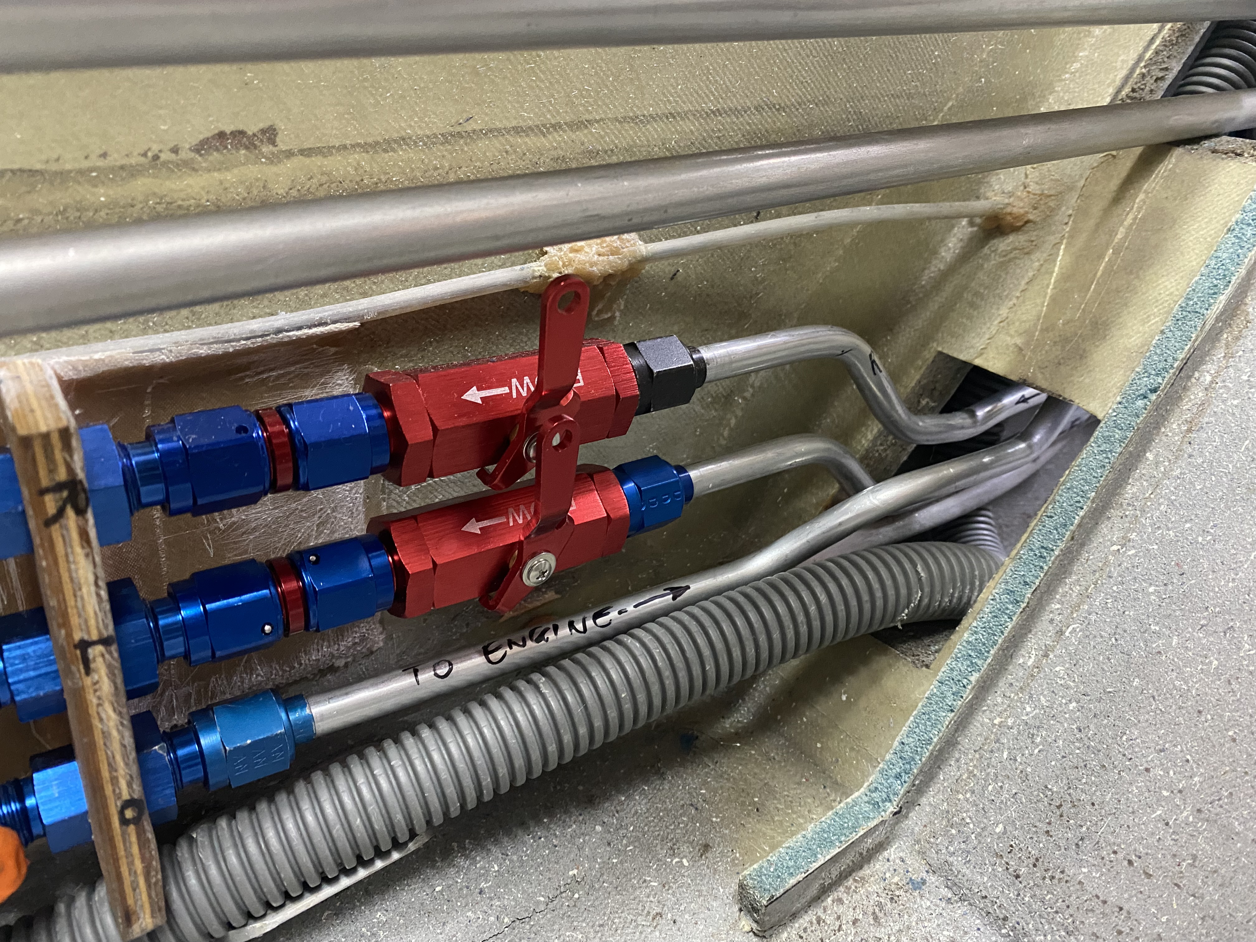
Fuel valves closed (maintenance scenario), and fuel lines installed
To reduce the likelihood of leaks, every connection got some of these inserts.
That came out well in my opinion, so it's time to move on to installing the pump.
I made some extra long click-bonds to bolt on the pump.
Stainless steel click-bond right off the lathe
Quickest way to liberate a click-bond
Four click-bonds necessary to mount the pump
Making vibration isolators out of leftover silicone baffling material
Test fit of silicone dampeners
Adding holes to help flox stick better
Holes and slots increase click-bondadhesion
Due to the scalloped shape of the floor, the right side of the pump would need standoffs to level the unit. I did this by contouring blocks of aircraft-grade spruce until they matched the shape of the raising floor, then floxed them to the floor.
Spruce feet roughed up to increase bond quality
Testing spruce risers' fit on floor
Floxing the wooden risers to the floor
Next step was to flox the click-bonds to the floor, and to the wooden risers.
Getting ready to install the click-bonds permanently
One could add some glass over it, but there are no forces acting on these.
Should any crack appear in use I can add some glass later.
Clear tape and washers will isolate the pump while the flox cures
Left side mounting arrangement
Overview of the mounting points
Clear tape and washer to create a flat flox mounting on which the pump will sit
Near click-bonds curing with pump weight on them
Finished pump mounts after two curing cycles
I then installed the silicone isolators, and did a trial fit.
Silicone vibration dampeners installed
A trial fit of the EFII pump in its final location
Although the fuel pump only required a coarse pre-filter (supplied), the fuel servo required a fine filter. I reused the fine filter (blue cylinder) JT already had, and mounted it right after the pump, moving weight forward, and centralizing the location of the items needing recurrent maintenance.
At this point, all there was left to do was bending and installing the fuel lines, and to help realize the complex geometry needed, I used aluminum welding rods as a proxy for the fuel lines.
With a little practice, fairly complicated shapes can be attained.
The aluminum welding rod makes the process of choosing a shape easier
I know it looks like an Exxon refinery, but it's just 2 tubes in, and 1 tube out.
I also had to build a new removable fuel valve bracket that stays attached to the valve at all times to facilitate the removal of the entire system.
Fuel valve mounted to the instrument panel bulkhead
Fuel valve and support bracket removed as a whole
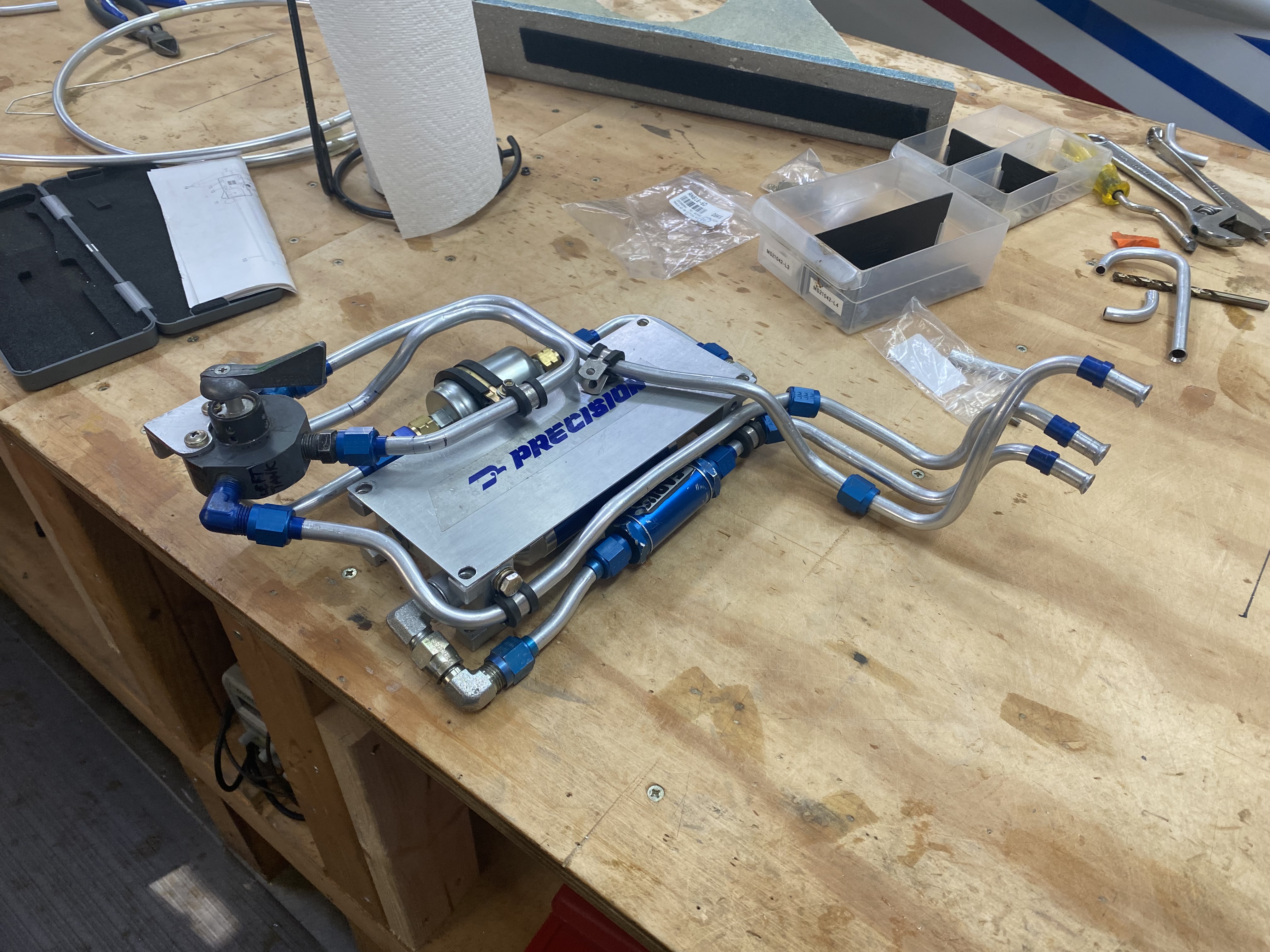
Fuel pump assembly removal
Fuel pump assembly on bench for fictional maintenance
A good look at the bottom of it
In the passenger’s compartment I chose to use Adel clamps instead of using another fuel bulkhead, then bent a few more lines to connect the tanks to the forward part of the fuel system.
In the back seat I cut the tank feed lines, and the to-engine line, and floxed in supports.
I bent more lines to go through the front seat
This is the final connection in order for the system to work
Front end of the rear compartment lines where they attach to the fuel bulkhead
With most plumbing completed, I decided to wire the fuel pump to the pilot’s stick via a dedicated relay due to the high pump amperage draw, and a quick wire disconnect device on top of the pump to be able to remove it.
Fuel pump relay at the top of the 3D printed relay rail
Electrical quick disconnect to the fuel pump
This is the finished product
Pump initial test
The last item left to install in order to call the plumbing complete was the Red Cube fuel flow sensor.
Normally the sensor gets installed between the Fuel Servo and the Flow Divider (spider) in the engine compartment. In this configuration fuel flow indications will faithfully represent fuel to the injectors (fuel being burned), and any mixture control movement will affect it directly. I chose to install mine in the passenger’s compartment downstream of the electric pump in order to have a cleaner and easier installation, and move as much weight as far forward as possible.
Because JT does not have a return fuel line to the tanks (by design), the fuel flow indicator in this location still accurately reflects the fuel flow to the spider (fuel being burned).
The only minor uniqueness of my installation is that I momentarily see a phantom spike of fuel flow indication when the pump is turned on (the opposite when turned off), even though the mixture lever is closed at the Fuel Servo, and no flow to the engine is present. The flow quickly returns to zero within a couple of seconds, so this is something easy to get used to, and does not create any real issues, but is worth knowing since it could be a little strange initially.
You don't want to use Teflon tape here
8-10 ft/lb
Ready for install
Red Cube in its final place
As much as I tried tucking the tubing out of the way, I was concerned for how exposed the tubes in the corner were to a stray foot, so I decided to fashion a kick-plate.
Cardboard kick-plate with foam and glass equivalent
Glued and curing
Rounded all corners
Glassed and sanded the joints
Installing mounting tabs for the rear of the front seat
Tabs glued to floor and seatback (lower left of image)
Kick-plate installed
Fuel lines shielded from wandering feet
Notch not necessary, but adds a couple of extra inches.
Well, I think this might have been long enough for a single post, and it was just the front half of the fuel system. We shall talk about the rear half behind the firewall another time.


No comments:
Post a Comment