Adding 12” of Y travel, a motorized Z axis, and so much more.
The main question is… WHY?
Why another foot of travel? Why spend time and money on a third axis for a 2D plasma cutter? Why not get on with it and finish JT’s latest mods? Why, why, why???
I suppose if I am to get off topic again, you all deserve an explanation, or two, to include… What the heck have I done in the past 12 months?
 |
| Chris and myself visiting BizMan after he started flying Scooter |
I will say that the amount of blog posts I’ll have to publish to catch you all up will take forever to get through, but I plan on slowly releasing updates and eventually bring you back up to speed with all that has been, and still is going on in the shop and with JT.
 |
| Flying on BizMan's wing |
Spoiler alert… after quite a bit of fun and flying, JT ended up in the shop again for the past year for major modifications.
No… not something I did.
All the mods you have seen, and a bunch more I haven’t even told you about yet, worked great, but the Ellison Throttle Body Fuel Injector started to show its age and give problems, precipitating the latest round of upgrades. But I shall tell you more about those in an upcoming post.
Today I’d just like to discuss the plasma table upgrades.
 |
| Basic Langmuir table (no water tray) |
I’m in need to cut a new firewall for JT (long story for another post), but anyone I asked either couldn’t handle it, or wanted too much money for it. Now, I would like it to look good and ideally be made of one piece of titanium or stainless, to that end I have painstakingly reproduced JT’s back end in CAD in order to mechanize the cutting of its firewall, which apparently I will have to do.
Unfortunately, while the firewall lays within the water table outline, the plasma torch itself cannot reach the far edge of the table, thus the firewall crown remains just outside of my plasma cutter's envelope (Y axis).
It’s always something!
Luckily for me, Langmuir (maker of my plasma cutting table kit) has come up with a few upgrades, one of which extends the Y rail about a foot, allowing the plasma torch to reach all the way to the far edge of the water table, bringing the top of the firewall back within cutting reach.
The other more expensive update has to do with adding a third axis. This will allow the torch head to move up and down to maintain the proper constant distance from the material to be cut, even when this material is a little warped and won’t lay flat. This is pretty common with thin, large sheets of metal as in a firewall 🤔, especially with the introduction of heat during cutting.
Without Torch Height Control (THC), the best case scenario in a warped sheet situation would be the torch being too high or too low at times, and the cut too shallow, or too hot melting desired features of the part. Worst case, the torch would end up way too low, crash into the sheet, and move it about the table.
None of these option is acceptable when the material cost gets high enough that one do-over would negate the savings of doing things oneself, but since the price of these mods would be about the same as getting someone else to do it for me... well, you know me by now 😁.
 |
| The loot arrives |
 |
| 2 axes v/s 3 axes Controller box |
 |
| Z axis and Torch Height Control (THC) hardware |
So, I embarked in another side project. Personally, I like to think of these projects as domino pieces that one has to carefully stack in order to achieve the end goal. To others they might look as a distraction… until their final purpose is revealed, that is.
I still remember people telling me to stop wasting time on my mill and lathe CNC conversions, but now the same folks tell me that I have it easy because I have a CNC mill and lathe.
Ha ha!
As I said… Domino pieces, ducks in a row, you know!?
Back to the matter at hand! Since the Z axis kit got here first, let’s mount that on the cantilevered X axis first.
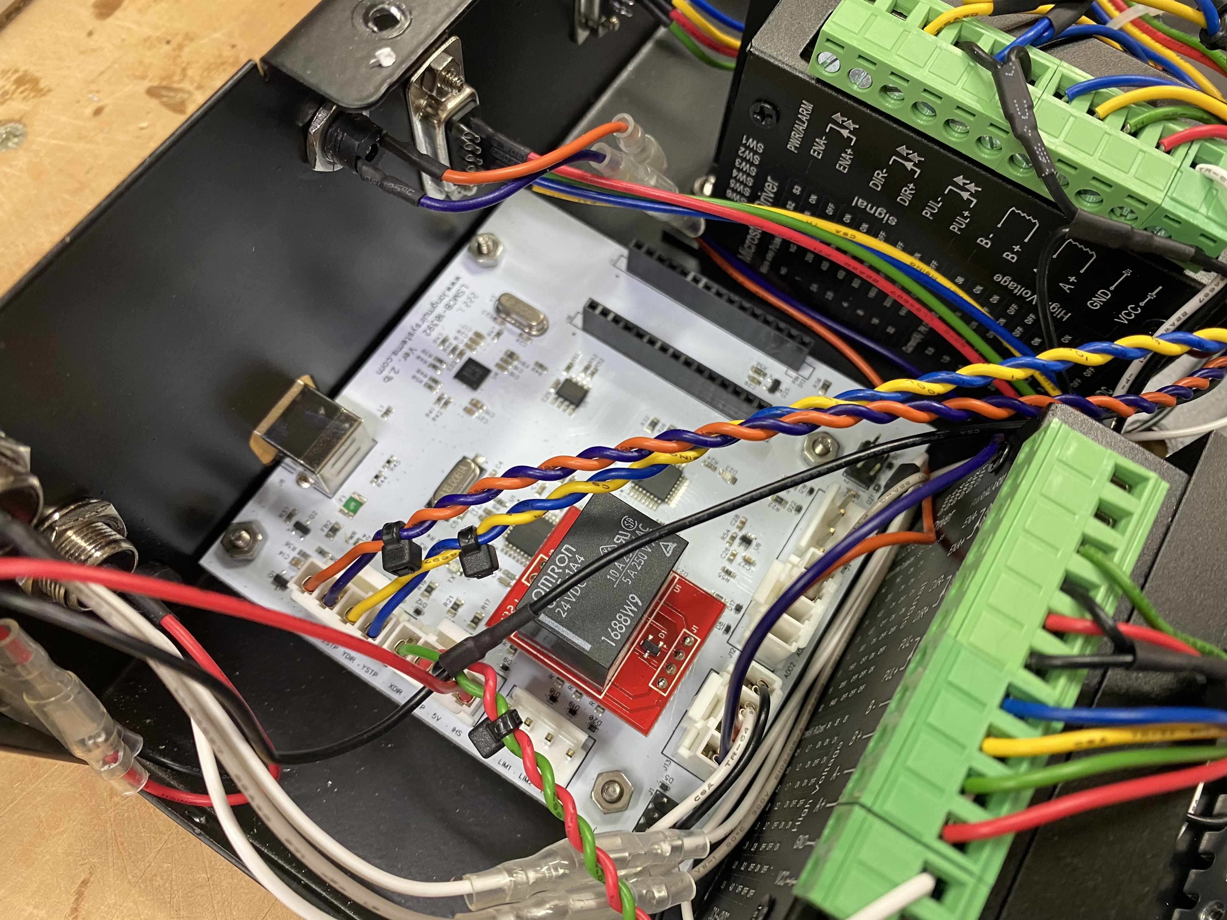
The Z axis required adding a Z Driver, and a THC electronic module. The new Controller enclosure had plenty of room for it all, so that part went pretty fast.
 |
| Controller box as it came from Langmuir |
 |
| Z axis Driver installed in Controller box |
 |
| THC electronic module |
 |
| Controller main board |
 |
| Main board with THC module installed |
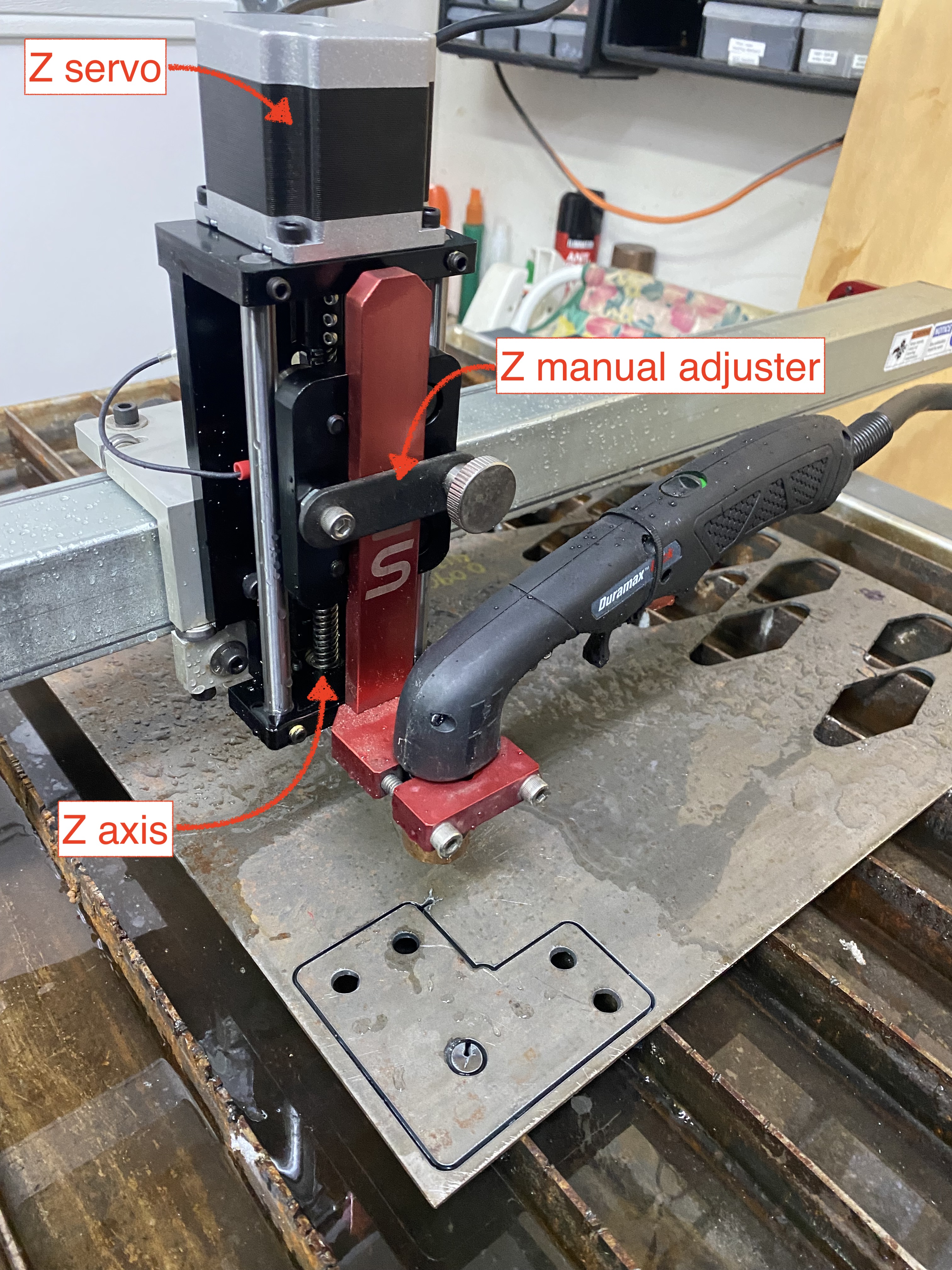
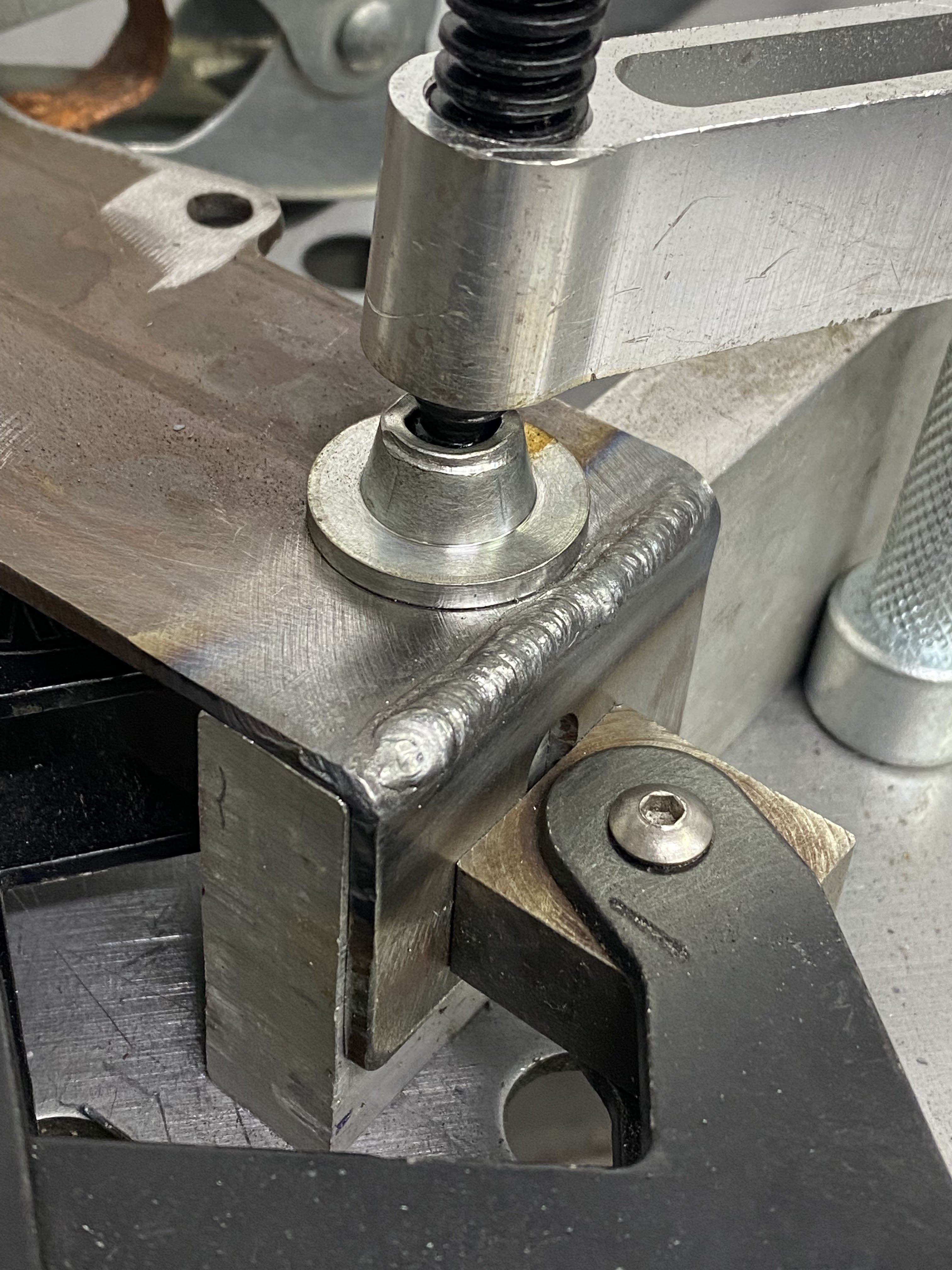
Adding the Z motor/axis took a little bit longer, but was still easy to do.
 |
| The original manual Z height setter |
 |
| The original Manual height setter gets reused on the new Z axis assembly |
Wiring the Hypertherm CNC port through the Voltage Input Module to the Controller box was explained fairly easily in the instructions, but with 220V and 50A on tap it is not something you wanna screw up.
 |
| Voltage input module wiring |
With the electronic addition completed, I moved on to other creature comfort items I long wanted to update.
Having a water table is a great help in keeping fumes down and parts from warping too much, and getting the water into the water tray is pretty simple, just borrow Gina’s gardening hose, and in a few minutes it’s done.
Getting the dirty water out of the tray however, is usually a mess. I usually just flip the table on its side say 60º or so, and dump it all onto my driveway, submerged metal trimmings included. Then it’s back to the gardening hose again to clean up the driveway, then pick up trash metal off the concrete, use a floor squeegee and a mop to cleanup the spill on the garage floor (now as slippery as an ice skating rink), then reinstall the little wheels that fell off during the tilting process… you see where this is going.
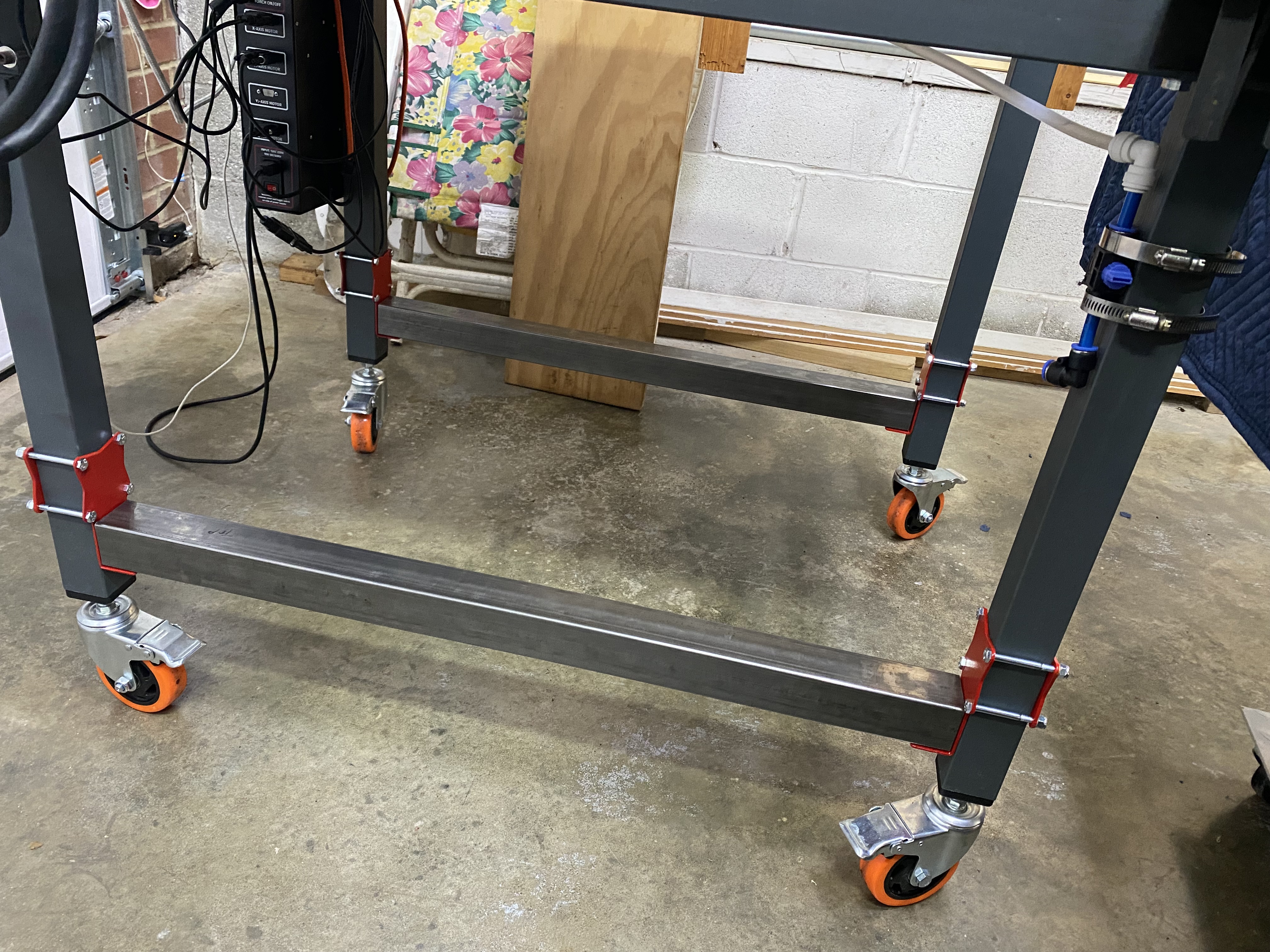
I decided to replace the tiny wheels with 4” tall ones, add a water drain with a hose leading to a tank.
 |
| Original wheels were too small, and liked to fall out often. |
 |
| McMaster-Carr item #60945K31 (½"-13 thread) |
 |
| New wheels installed. Fit was perfect. |
Ideally the tank would remain with the table at all times, so I added a bottom tray to hold the tank and the plasma cutter to my list of upgrades.
 |
| Lower tray design in CAD |
As for the the leg braces that would support the tray, I started with a design Lyle shared on the Langmuir FireShare website, and lengthened it by about 2”, then cut it out of a mild steel sheet, bent it, and welded it across the bending slot for strength.
 |
| Bending the plate at the slot |
 |
| Our EAA Chapter's bender |
 |
| All plates bent at the slot |
 |
| TIG welding the slots shut |
 |
| The setup for welding |
 |
| Outer corner weld |
 |
| Inner corner autogenous weld |
 |
| All plates welded up |
 |
| Another look at the plates |
 |
| Buying hardware to join the plates |
 |
| Priming the plates |
 |
| Painting the plates |
 |
| The final product |
 |
| Support plate mounted on a leg |
 |
| Back side of the assembly |
 |
| All four support plates mounted |
The tray itself was made from scratch out of 2x2 and 2x1 steel beams. I started out by cutting, drilling, and adding threaded inserts onto the two main X direction beams.
 |
| Time to get this bottom shelf started! |
 |
| Drilling clearance holes for threaded inserts |
 |
| Threaded insert before installation |
 |
| Permanent installation of the insert |
 |
| What a threaded insert installation looks like |
 |
| Testing the insert with a AN3-4 bolt |
 |
| X direction beam installed |
 |
| Bottom shelf securing strategy |
Then I fitted three crossbeams, and tack-welded them together in place before moving the whole assembly to the welding table.
 |
| Test fitting the bottom tray's crossmembers |
 |
| Removing the tray for further welding |
 |
| Tray's temporary welds |
 |
| Getting ready to weld the main structure of the tray |
I mostly used the TIG welder on this project, up until I got to welding the 1x4s, and by that time I had ran out of Argon gas, so I switched to my brand new MIG welder for the first time.
 |
| Tig weld |
 |
| More TIG welds |
 |
| Main structure welded |
 |
| 1x4 stringers |
 |
| Cutting the stringers |
 |
| Setting the stringers up for welding |
 |
| MIG welds came out better than I anticipated |
 |
| Main bottom shelf structure welded |
 |
| Expanded steel support welded to the shelf skeleton |
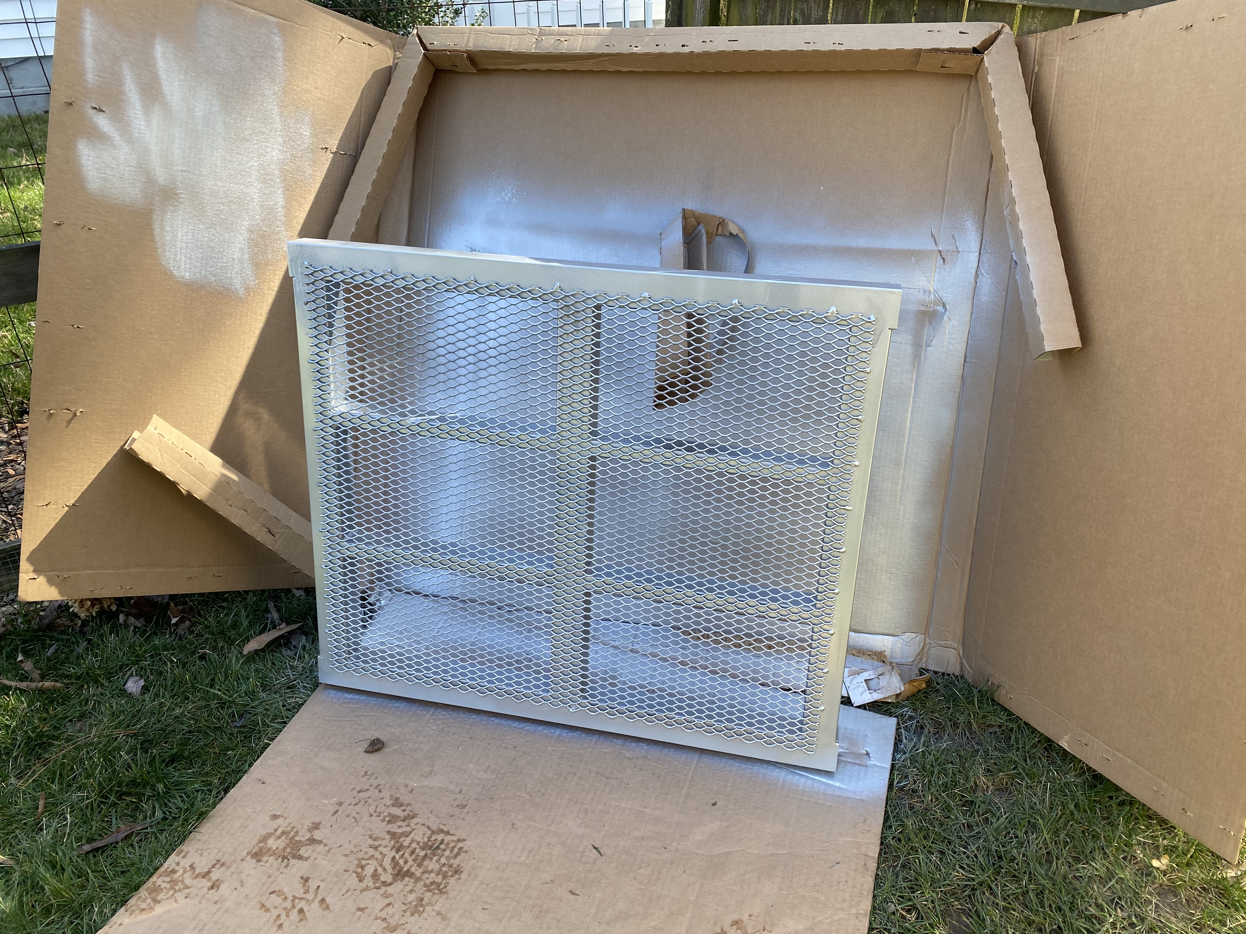
I was going to leave the tray be, but with water right over the top I figured it would turn to rust in no time, so I primed it, and painted it. I am glad I did, because I really like the way it came out.
 |
| Temporary paint booth |
 |
| Shelf primed twice |
 |
| Top of shelf painted a Titanium silver |
 |
| Same color on the bottom |
 |
| Bottom shelf finished and installed at last |
 |
| Another look at the installed tray before wiring the table |
Next item on the upgrade list was to recess and create a new drain.
I 3D printed a dimple die design Mrak shared on FireShare, and used it to dimple the waterbed.
 |
| Dimple die made out of Polycarbonate ABS. Good enough for a few squeezes. |
 |
| Central drain visible with slats removed |
 |
| Future drain hole before dimpling |
 |
| Bottom die in place |
 |
| Top die before squeezing |
 |
| Top die pulled tight to dimple the water bed |
 |
| Clearly visible dimple in the water bed |
The new dimple in the bed allowed the original brass fitting to fit flush in order to better evacuate the water.
 |
| Brass plug reinstalled (with silicone paste) minus the original rubber seal |
I removed the zinc plug and threaded a ¼” NPT fitting to a faucet, and then to a spare bucket, I mean… tank, I had in the shop.
 |
| Tray survived the water buffalo test 😂 |
 |
| A 5 gal bucket holds all the water, and it's easy to dump it back on the tray. |
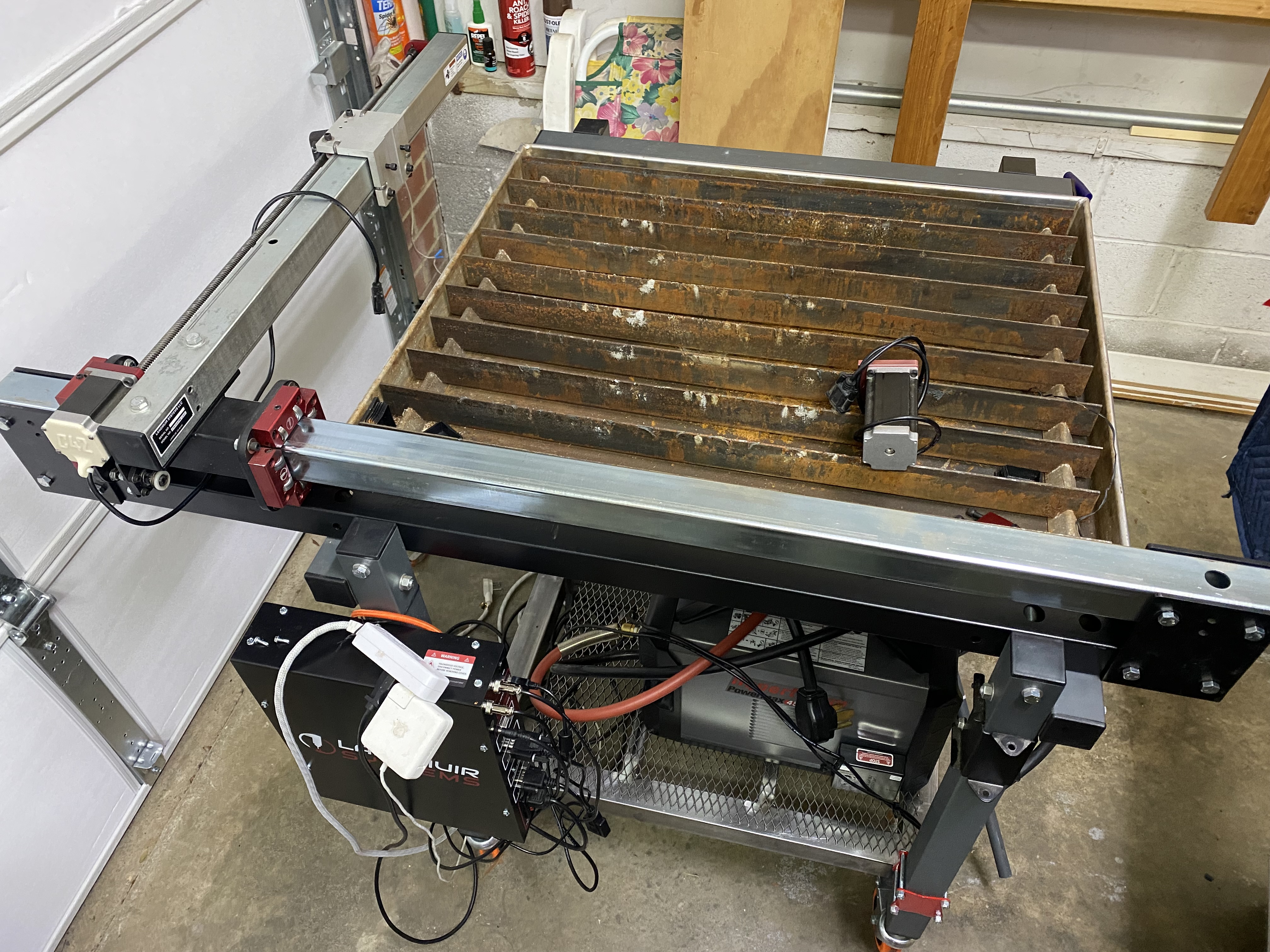
When the Y axis extension showed up, I quickly installed it, and was ecstatic to see that now every inch of the water table is within reach of the plasma torch.
 |
| Y axis extension delivered about a month later |
 |
| Y axis extension items |
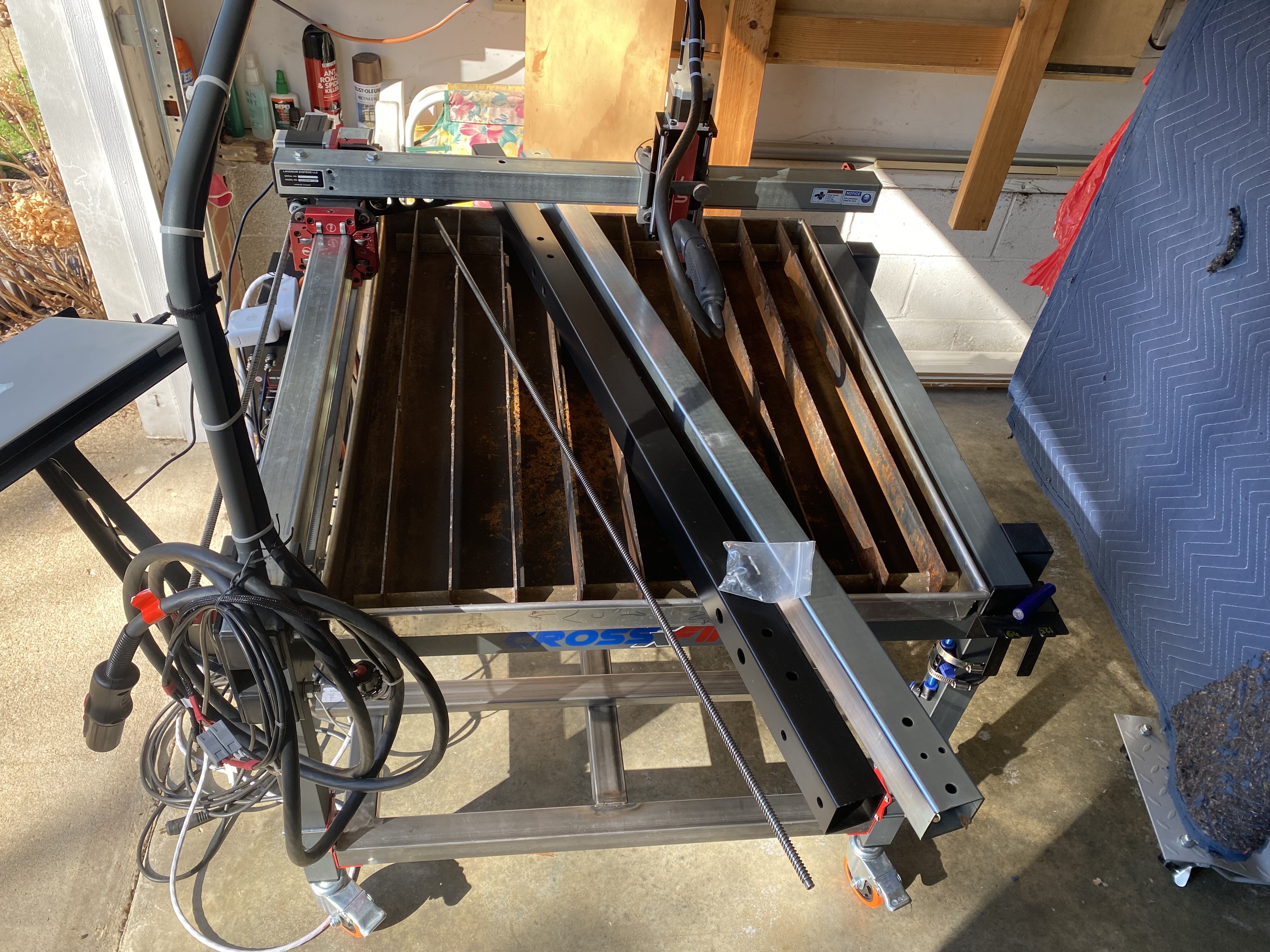
First I had to remove the existing shorter Y axis and support beam.
 |
| 2x2 beams removed |
 |
| About 1 foot difference in length |
With the longer ones installed you can see how much space was gained with this upgrade.
 |
| Y axis shuttle able to move (to the left in this photo) much further now |
Last but not least, I decided to make a new mount for the laptop. I did this because the normal mounting is 90º off of the table, and I always end up jogging the Y instead of the X axis, and running into things because of that.
I reused a piece of the short Y axis support I had just removed to create a new place to mount the laptop stand.
 |
| Repurposing the 2x2 beam removed from the table |
 |
| The beauty of this piece is that some holes already lined up |
 |
| However, they needed to be slightly enlarged. |
 |
| The fit is tight, and I noticed a little rubbing between components |
 |
| Adding a relief hole made it all better |
 |
| The new down-tube will offer a better mounting option for the laptop, and pathway for wires. |
 |
| Laptop stand mounted. The hollow down-tube will house some of the wiring. |
This plasma table finally started to look like it meant business, so I decided to tuck the wiring out of sight as much as possible, and prevent the mess of cables I used to trip over in the past.
 |
| This wiring mess was one of the problems I was trying to solve with the tray mod. |
 |
| I think the wiring is much much better now |
 |
| The use of cable raceways cleaned up the wiring immensely |
 |
| A 110v cable, one 220v cable, and an air hose are now the only table's tethers. |
 |
| Wire management in action |
 |
| Air and electrical tethers |
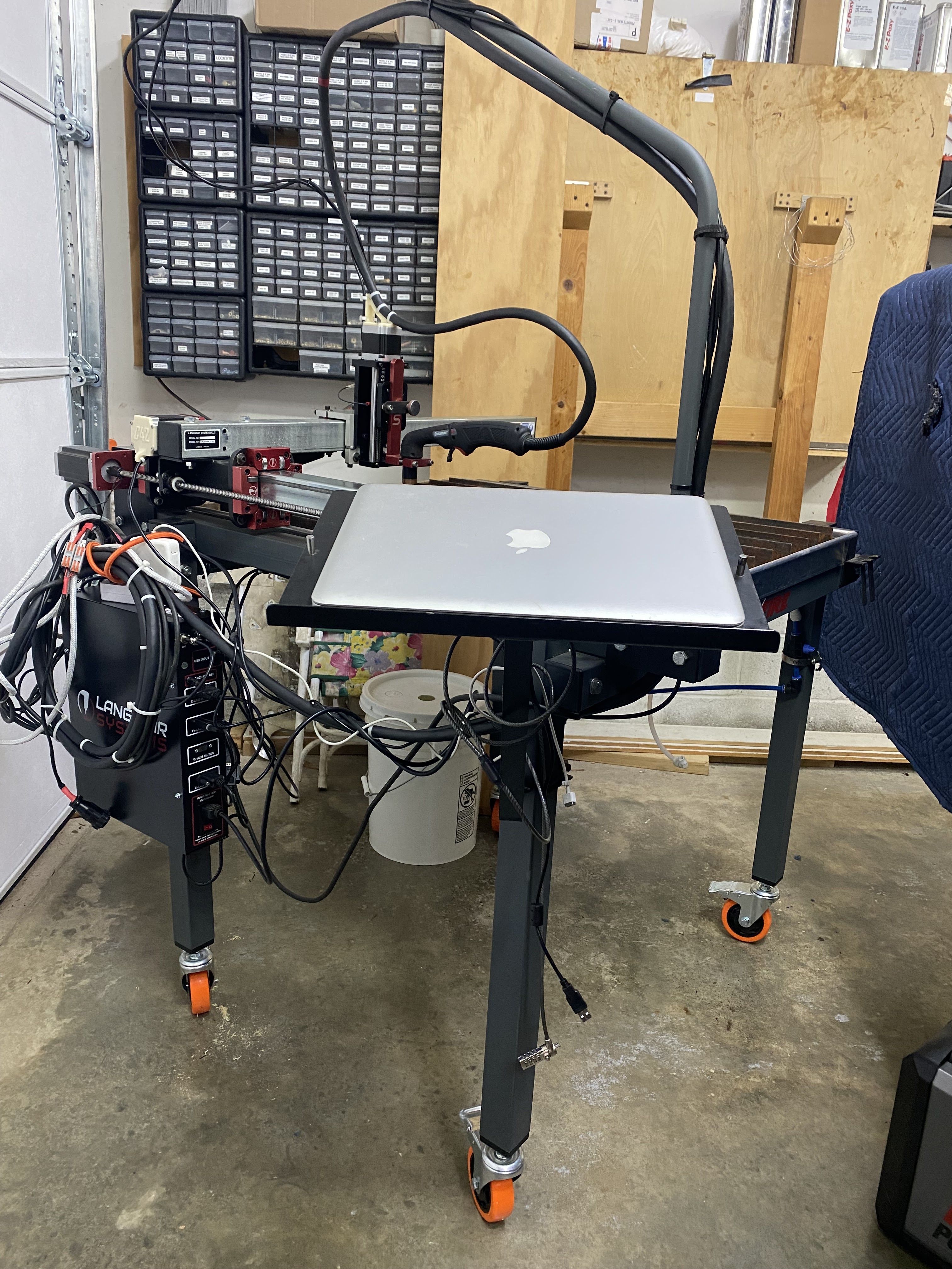
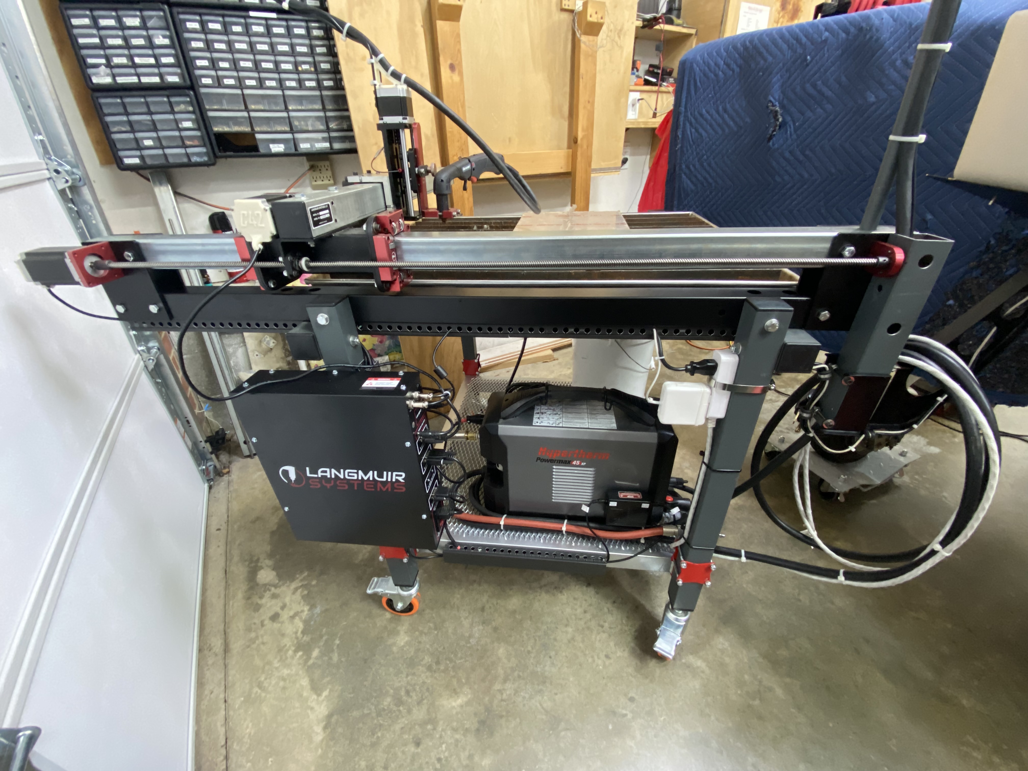
 |
| The plasma table is now a self contained unit able to be moved about and used as needed without further setup |
While I should have been content with what I had achieved thus far, there was one more improvement I wanted to make in order to make lining up of the torch on a point more precise.
I designed and 3D printed a holder having the same outer diameter as the plasma torch, and the inner diameter to fit a 9mm laser. Substituting the laser device for the torch, when accurate alignment is needed, will allow to jog the table much more precisely than how I’ve done it thus far… eyeballing it.
 |
| This laser fits 9mm handguns |
 |
| The laser will be used to align the plasma torch to a starting point when higher precision is needed |
 |
| Old firewall on plasma table |
 |
| Example of using the laser for accurate plasma torch alignment with a feature |


No comments:
Post a Comment