Motion control system
Here’s an overview of the electronic interface between the computer, and the stepper motors now attached to the mill.
 |
| Synoptic view |
To keep things simple, I opted to go with a Gecko G540 unit.
The G540 is a complete 4 axis system which plugs directly into the computer via the parallel port, and to the motors through DB9 connectors. It contains four G250 motor drivers, and a breakout board in a hard anodized aluminum case. It’s slightly more expensive than buying individual components, but it’s compact and powerful, and saved me from having to do a lot more wiring.
In addition to the 4 axes, the G540 also supports spindle control, multiple E-stop kill switches, limit switches, flood coolant, charge pump, etc. Because of its size though, it has the tendency of running hot, so cooling fins and a fan are a very good idea.
 |
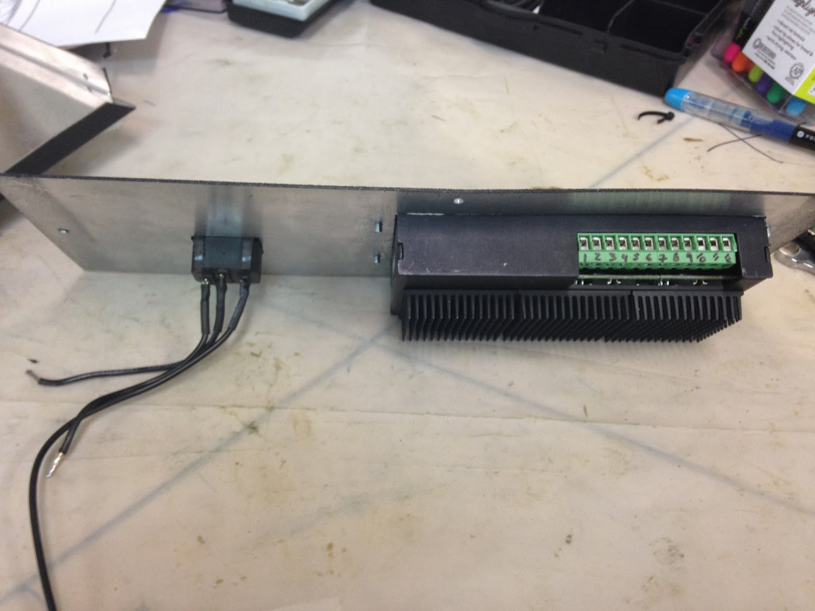
| Gecko G540 4 axis stepper motor driver |
 |
| G540 back side with cooling fins attached |
 |
| This 48vdc cooling fan will extract hot air from the enclosure |
 |
| Air intake into the box (near power supply) |
More voltage to the drivers equals more torque at the motors, so I chose to go as high as the Gecko would allow (50vdc max) and purchase a 48vdc 12.5amps power supply.
 |
| 48vdc power supply business end |
 |
| Power supply info |
Time to put things together...
 |
| The power supply takes up most of the space inside the case |
 |
| G540 and plug receptacle added to the rear panel |
 |
| Back of the case |
 |
| Emergency kill switch and ON/OFF switch added to the front panel |
 |
| Wiring it all together |
 |
| Finished motion control system |
With the driver enclosure completed, the task of wiring the motors remained.
I chose to use insulated wire, to minimize stray induced currents coming from the motors, and terminate them with a DB9 plug suitable for connecting to the Gecko.
One thing the Gecko manual warns about is to use a 1/4 watt resistance between pins 1 and 5. The value of this resistance is to equal the motor’s amperage times 1000. In this case 3.5kΩ. Without this resistance the motors would not go into current standby mode which would result in increased motor heating.
 |
| Adds up to 3.6kΩ, but that's close enough! |
 |
| Resistors heat-shrunk, and plug ready for closing. |
 |
| Wiring and motor ready for testing. A liquid resistant connection will need to be deviced later. |
The final connection between the Gecko and the computer is typically done via a male to male parallel port, a slow ancient technology that can be only found online anymore.
Since I’d like to eventually use a laptop to run the mill, I purchased a USB to parallel port interface from CNCdrive motion controls. This is actually an integrated circuit board that fits inside a parallel port outer casing, and is capable of running time critical commands thus removing considerable processing load from Windows.
 |
| 21st century interface to a 20th century technology |
As soon as the DB25 is delivered, I'll connect the computer, and start testing the motors with Mach 3 CNC controller software. If all checks out ok, I'll put the motors back on the mill for a trial run, then start working on how to integrate the limit switches into the mill, and wire them into the G540.


No comments:
Post a Comment