Landing brake - locating (2.0 hrs)
The Long EZ is a slick composite aircraft in many ways, beside its looks.
Compared to a regular production airplane, the drag acting on the airframe is very small, while its efficiency is very high, such that the power off descent rate is almost worthy of a glider. If I remember correctly, I think it was Mike Melville who wrote in one of the CPs about turning the engine off, and soaring the thermals for hours, while actually gaining altitude.
All of this is a good thing, until it’s time to land.
Just as gliders have spoilers to kill some of the lift, and allow them to steepen the approach for a normal landing, so does the Long EZ need a way to increase its drag, and reduce the glide ratio for landing.
The way the Long EZ accomplishes a normal approach, is by deploying a landing brake. This device is built into the belly of the airplane, and obviously acts to increase drag, but it can also be thought of a maybe-not-so-efficient flap. And just as a flap, slower steeper approaches can be achieved to shorter runways, while minimizing wheel brake usage after landing.
It probably wouldn't shock anyone at this point, if I mentioned that the relevant information on the landing brake are scattered over a few different sections, chapters, and CPs. So, a little research is required before even being able to determine its proper location and size, let alone building it.
Part of the reason behind this difficulty is that the landing brake was initially designed for the Very EZ, the smaller airplane from which the Long EZ was derived. In the Long EZ, the brake dimensions were increased by roughly 10%, the type of foam was changed, the embedded wooden parts were enlarged, and a host of other changes to the attachment and deploying mechanisms were adopted over time.
Since I will be using an electric actuator to operate my landing brake, I am spared a lot of complicated ancillary fabrication, but I will have to come up my own set up.
With this blog entry I will just lay the foundations of what will become the landing brake.
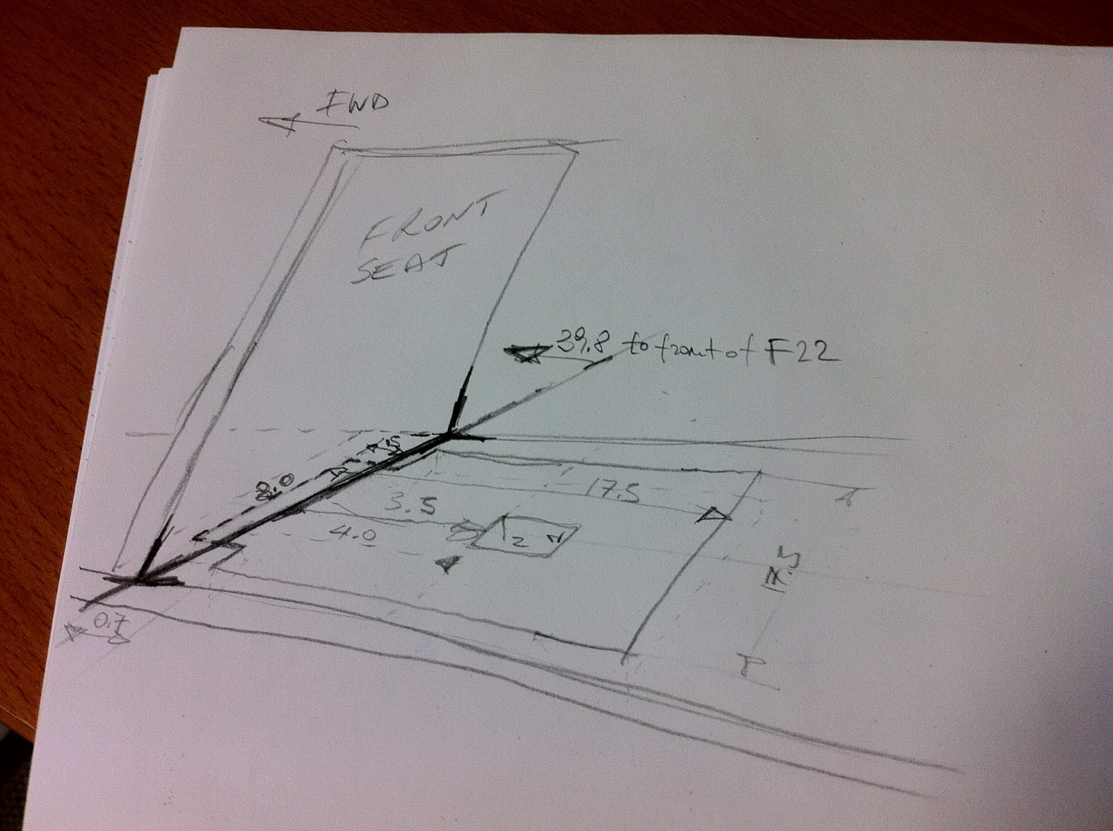
First on the list was converting all the mumbo-jumbo in the plans into an actionable sketch.
 |
| It all make sense now, I think! |
I must point out that my landing brake will end up 2” (5.08 cm) ahead of its normal position, due to the fact that my front seat is 2” further forward than the plans call for. Furthermore because my fuselage is also 2" wider, other EZs measurements might be a little different than mine, like the distance to the front of F-22 for example.
The next step was to transfer these measurements to the actual fuselage.
 |
| "Measure twice, draw once!" |
Even as careful as I was, I was still able to mess it up. Fortunately, I caught the small mistake before glassing the fuselage.
 |
| "Ok, draw twice!" |
Packing or duct tape is placed over the landing brake, and since fiberglass will not permanently stick to the tape, I will be able to cut and remove it in that area after the outer fuselage is glassed and cured, at which point the task of actually building the landing brake will begin.
 |
| Applying fiberglass release material (aka packing tape) |
 |
| Tape cut to size with a razor blade |
 |
| Mmmm... that nose gear hole is not very symmetric. I'll have to fix that! |
In preparation for glassing the outer fuselage, and to help make this long layup less difficult than it has to be, I have built a few more aids with my limited carpentry skills.
First on the list is a way to rotate the fuselage ±45˚ along its longitudinal axis. This requirement is actually spelled out in the plans.
So, I modified my saw horses for the task to come.
 |
| Rea hinge mechanism |
 |
| Front hinge |
 |
| Piglet ready for roasting! |
Initially only half of the fuselage is glassed.
Still fairly wet after curing for a couple of hours, but to the point that the cloth will no longer fall off as the fuselage is rotated to the other side, the opposite side is glassed.
Although one or two helpers would be advisable, this layup can and has been done solo, and that’s probably how I will do it as well.
Carrying big pieces of fiberglass from my cutting table to the fuselage without disrupting the weave, would have likely been impossible on my own, so I repurposed some previously used 2x4s, and made a mobile stand for the UNI.
 |
| Mobile UNI dispenser |
This stand will be dragged around the fuselage as needed in order to dispense the cloth.

Really cool Marco, and looking great! Can I have a ride??? :) I love your idea for the conduit - very slick solution.
ReplyDeleteThanks, your name has been added to the very short list.
ReplyDelete