Chronicling my Long EZ construction (and a few other things).
Disclaimer
This blog is for entertainment purposes only, and is not meant to teach you how to build anything. The author is not responsible for any accident, injury, or loss that occurs as a result of reading this blog. Read this blog at your own risk.
Monday, September 25, 2017
Ch 22 - Electrical/Avionics - Part 10
"Git her done!"
So much to talk about… so little time.
Wade and I just returned back from Rough River, and had an awesome time. Yes, we did fly there and back in the Long EZ, which means you and I have a lot of catching up to do, don’t we. So, hang in there as I try to bring you up to date.
I resigned myself to be carrying a perfect usable roll servo (from the the removed Trio autopilot) to Rough River and back, even though I would not be able to use it since it does not interface with the Mini-AP, thus I started closing the hole I had just opened in the last blog entry.
Foam removed to make a flox corner
The flox corner will withstand the screws torque better than the foam/glass sandwich
Autopilot hole being closed up
I decided to peel-ply the whole panel to get a different texture than the glass weave
Peel-ply removed, lot of trimming and sanding to do.
One item I yet had to find a place for was the ARINC module. Looking around behind the panel, I noticed the unused bracket where the vacuum regulator filter used to be mounted, and it seemed perfect for the new box.
Trying to reuse an existing bracket
Now I just needed to come up with a permanent way to keep it there.
The new ARINC mount
The way it should work
I decided to 3D print a fitted mount out of ABS.
I printed it in the standing configuration
This 3D printer never ceases to amaze me
So glad it fit
The fit turned out great for once, and I moved on to the next item on my list… the OAT (Outside Air Temperature) probes.
A while ago, I chased two lose wires to a hole in the wheel well glass enclosure filled with silicone and what looked like an old temperature probe. The hole turned out to be perfect sized for the GRT probe, so I tried it there and liked both the clearance with the wheel, and the position of the wires as it related to the new panel.
I ended up mounting both probes near each other.
Two OAT probes installed in the wheel well
Plenty of clearance with the nose wheel
Problem solved!
You might remember my OATs wires are part of the Magnetometer bundle, so I started looking for a good location for it. I was worried I’d have to remove a wing to put in in the wing root the way most builder do, but acting on a suggestion from my friend Walter, I decided to test it below the pilot’s thigh support.
That spot seemed made for the magnetometer, with two existing brackets perfectly positioned for a box its size, and the closest steel part 6” (15 cm) away, and very small. I used a small leftover piece aluminum to make an adapter for it. The magnetometer seemed rock solid and perfectly aligned with the aircraft centerline.
Magnetometer mounted under the thigh support
Another chance to reuse an existing bracket
Next on my list were the radio mounting brackets. I laid a 14” (36 cm) six ply BID layup on an aluminum L channel, and the next day I had two strong 7” (18 cm) radio mounting bracket blanks. I fitted them to the panel, then added nut plates to hold the radios.
Clamping the fiberglass bracket in place
Bracket seen from behind the panel
Radio brackets bolted to the panel
The right bracket was profiled to match the panel's shape
Nut-plates riveted to the bracket and radio trays installed
Trays mounted to the panel
GPS/NAV/COM and transponder installed
One problem that cropped up at this time, was that the intercom would no longer fit above the radio stack, but since I wasn’t planning on using the autopilot anymore I decided to make an adapter plate, and use its spot for the intercom instead. Yes, I'd have to reopen the same hole I had just closed. 😤
Intercom's new temporary position
New intercom face plate
Intercom installed
Intercom in the panel
Front view
Finished intercom placement
While the panel was apart, I decided to relocate the flap switch to a place I could more easily get to during a go-around event. Because the switch looked like all the other switches on the panel, I decided to make it more distinct by fashioning a cover in the shape of a flap out of a piece of scrap aluminum.
Band-sawed aluminum scrap...
... belt sanded into a pleasing flap shape.
The Landing Brake switch is pretty obvious
Demonstrating the "new" landing brake switch
Another issue that cropped up during testing was that only four of my warning lights behaved as they should have. Solving this ate two precious days, and put the planned trip to Rough River in jeopardy.
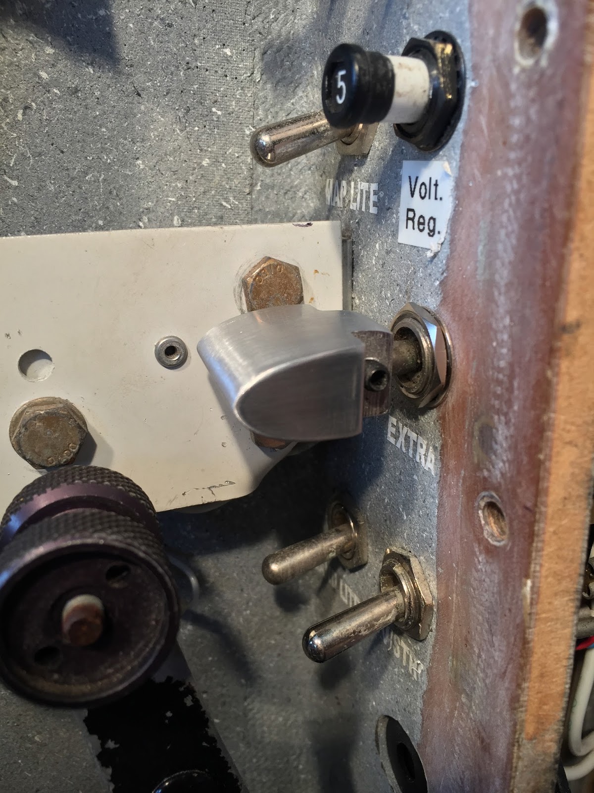
The “Voltage Low” light was restored to proper functioning through the use of a relay (thanks Nick).
Main Bus to the left, and Voltage Regulator to the right.
The wild behavior of the “Gear/Canopy” light and horn was corrected by removing it from the Press-To-Test circuit. I later reworked my PTT circuitry, and I plan on remaking the whole board the next time around.
Relay added to the "Gear/Canopy" light
The last big issue I ran into was that the GPS would not lock on to any satellite, even after 30 minutes of trying. To make a long story short, I eventually found that the shielding on the cable that came with the GPS tray did not connect well (thanks Jerry).
GPS unable to connect to satellites
This was an easy fix that unfortunately consumed another precious day, cutting it now very close to our planned Rough River departure.
Enough satellites to get a fix established
One last minute addition to the new panel was a pair of Dsub connectors to make the PTT easily detachable from the rest of the plane, and be removed as one unit with the panel for maintenance.
Completed panel
The day before our departure I reinstalled the canard, and recalculated the weight and balance, which turned out to be 4.6 lb (2 kg) lower. When Wade arrived from D.C. we calibrated the magnetometer, then I went for a test flight.
I orbited the field for a while, then tried the new ILS function by shooting the first practice precision approach this plane has ever seen.
Awesome!
The next day we left for our trip… dare I say it turned out to be one of the best Rough River fly-in in recent memory… and flew 1000 NM (round trip) without any issues whatsoever.
There is so much information on those little screens, I felt like I was watching three movies at the same time, but eventually I got more and more used to them, and I am now totally sold on them. I can hardly wait to get the two autopilot servos installed and do some more flying.
Here are a few shots of the panel I took during the flight…
Demonstrating the HITS (Highway In The Sky)
GPS navigation with HSI+RMI
GPS navigation with MAP mode (North Up), HITs (Highway In The Sky), Flight Director, and flight path marker.
GPS nav with MAP mode (Track Up), and HITS.
GPS nav with HSI+RMI (green), and VOR RMI (white).
VOR nav with HSI+RMI (white), and GPS RMI (green)
GPS nav with HSI+RMI (green), and VOR RMI (white).
GPS nav in HDG mode (060°), with HSI+RMI (green), and VOR RMI (white).
No updates in a while? Hope everything's OK and that you haven't lost traction on your build! Since my own Long-Ez build is totally stalled it keeps my hopes up reading about your progress.
All is well with me, and I do feel guilty for not having posted since the Rough River trip.
To date I have installed the roll servo in the flying EZ and have been spending the last few months troubleshooting the two EFIS. I have found some issues that required software fixes from GRT, and others that were settings related, but we are getting them ironed out.
I have two gripes left as of now, but they are fairly minor. The main one is the premature shallowing of the bank angle as the plane approaches the commanded heading. This might be ok flying VFR, but it would be an issue IFR. GRT knows about it and I'm awaiting a software fix. The other is that the autopilot disconnects when I switch it from top EFIS to bottom EFIS. It seems to work only if I also switch the bottom EFIS to PFD. I haven't got an answer to that one yet.
I didn't want to post all of these teething issues because they are to be expected with cutting edge equipment, and they would make people steer away from a very good product that would be fixed by the time they read my review.
I am still very happy with my decision, and have been shooting all kind of approaches so far, trying to figure out the radio and the EFIS. I shot some video of a couple of approaches and put them on YouTube, you should check them out (search for crivo152).
I plan on catching the blog up pretty soon, then hopefully stay on top of it.


Hey Marco,
ReplyDeleteNo updates in a while? Hope everything's OK and that you haven't lost traction on your build! Since my own Long-Ez build is totally stalled it keeps my hopes up reading about your progress.
Hey Lutorm, thanks for dropping a note.
ReplyDeleteAll is well with me, and I do feel guilty for not having posted since the Rough River trip.
To date I have installed the roll servo in the flying EZ and have been spending the last few months troubleshooting the two EFIS. I have found some issues that required software fixes from GRT, and others that were settings related, but we are getting them ironed out.
I have two gripes left as of now, but they are fairly minor. The main one is the premature shallowing of the bank angle as the plane approaches the commanded heading. This might be ok flying VFR, but it would be an issue IFR. GRT knows about it and I'm awaiting a software fix. The other is that the autopilot disconnects when I switch it from top EFIS to bottom EFIS. It seems to work only if I also switch the bottom EFIS to PFD. I haven't got an answer to that one yet.
I didn't want to post all of these teething issues because they are to be expected with cutting edge equipment, and they would make people steer away from a very good product that would be fixed by the time they read my review.
I am still very happy with my decision, and have been shooting all kind of approaches so far, trying to figure out the radio and the EFIS. I shot some video of a couple of approaches and put them on YouTube, you should check them out (search for crivo152).
I plan on catching the blog up pretty soon, then hopefully stay on top of it.
Ciao, Marco.