Disclaimer

This blog is for entertainment purposes only, and is not meant to teach you how to build anything. The author is not responsible for any accident, injury, or loss that occurs as a result of reading this blog. Read this blog at your own risk.

Monday, September 21, 2015

Center section spar - part 3

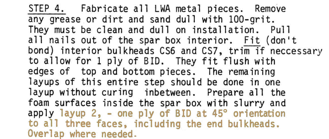
Understanding the layups of Step 4 (3.2 hrs)

Everyone I’ve talked to has told me to take my time here, and to make sure I understand what the plans are trying to say with regards to laying fiberglass inside the spar.

That is of course always good advice, but more so than ever in this section of the build. I feel strongly that if a second edition of the plans had ever come out, Burt would have reorganized this section to make it clearer.

Since that never happened, I will try to break it down and present each layup separately, so that the designer’s intent might become easier to understand. Hopefully by the end of this you will think it was not so difficult after all. 

One important aspect of this layup is that it is required to be completed all at once, without curing in between. Make no mistakes, this is a bigger job that it might initially appear to be, especially if you work alone as I normally do. 

As usual, all BID is laid up at a 45˚ bias with all surfaces (bulkheads included). Also, in this post the terms UNI and UND  will be used to refer to the same unidirectional fiberglass.

I am going to pick step 4 apart now, but first a warning...

The text and drawings below have been highly modified from the originals (sometimes down to the individual pixel level) for demonstration purposes. DO NOT use these as reference to build a plane. 

There you go, I've said it!


Starting layup covering the entire inside of the spar

Layup #2 is pretty easy to understand, it’s just a 1 ply BID layer covering all inner surfaces, time consuming but straight forward.


Adding the inner bulkheads

Very well, when time comes to insert the foam bulkheads CS6 and CS7 27” (68.6 cm) from centerline, they must be perpendicular to the aft face (bottom in the jig). Let's mark their locations now.


Using a foam scrap to outline the inner bulkhead position

Making the bulkhead perpendicular to the aft face (bottom in the jig)

So far so good. Layup #3 coming up next requires more attention and planning as it slightly differs depending on whether you are working on the inner bulkheads (CS6 and CS7), or the outer ones (CS5 and CS8).

I will color match the text, the drawings, and the photos with the intent making them easier to associate with one another. You should know that not all components of layups 3 and 4 appear in the original drawings (and these modified ones as well), perhaps for clarity sake.

Let’s consider the inner bulkheads first.


Most (not all) of layup #3 plies show up in the drawing

As you can see, while the first ply of BID goes on both sides of the bulkheads, they only appear on one side of the bulkhead in the drawing. So, the smaller BID ply goes on the outboard side and covers the bulkhead, lapping 1” (2.5 cm) on all other surfaces.

Laying on the opposite side, the bigger ply covers the bulkhead, then laps 5”  (12.7 cm) onto the top and aft faces (aft and bottom in the jig), but only 1” (2.5 cm) on the bottom face (forward in the jig) since there is no attach point here. Ok, to be picky there is no attach point on the top face either, but the drawing clearly shows BID up there.

A demonstration might help here, so I made a cardboard template to simulate the BID ply, and to be used later to cut the fiberglass.


Making the template for cutting the fiberglass

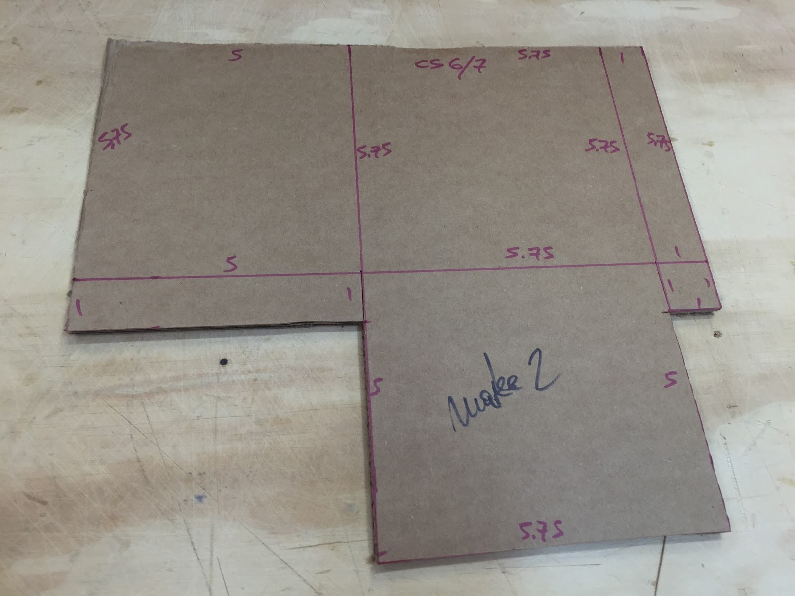
I will use this to cut two BID pieces, one for CS6 the other for CS7

This is how the first part of layup 3 should go on


Now three plies of staggered UNI 10, 8, and 6 inches (25, 20, and 15 cm), are laid over the top and aft face (aft and bottom in the jig) where the hard-point will go next, with the fibers direction going front to back along the longer dimension.

After floxing the aluminum plate, the last layup consisting of one ply of BID goes over the top of the anchor point, and extends 1” (2.5 cm) in all directions.

So, here’s what we’ve got so far…


Color coded to match the layup description above

Same layup schedule seen from the opposite side

Easy, right?

Ok, let's move on to the outer bulkheads of the center-section spar now, CS5 and CS8. Once again I will color match text, drawings, and photos, and also modify the drawing to include Long EZ plan change #28.

LPC#28 (published in CP#25) clarifies the edge distance of the aluminum anchor points from the bulkheads... Outboard LWA 1 (sketch on left center of page) 1.0" dimension should be to outside of CS 5 and 8, not inside. Change inside dimension to 0.75". Be sure to transition edges of all metal parts with flox.


Most
 (not all) of the outer bulkheads layups (including LPC#28)

The first BID ply goes on the bulkhead as before, but this time around it laps 5" (12.7 cm) on all other foam surfaces equally.

The UNI plies that go on next are staggered the same way as before, though they are slightly longer here, and extend over both top, rear, and bottom (aft, bottom, and forward in the jig) of the spar.

Two aluminum plates are floxed at this stage, and the usual BID at 45˚ bias is laid over them extending 1" (2.5 cm) in all directions. 

With the distance from LWA1 to the bulkhead now reduced to only 0.75" (due to LPC 28), the BID over LWA1 ends up lapping ¼" onto the bulkhead to achieve the "before-LPC-28" required 1" overlap in all directions

Lapping up the bulkheads was not the original design, but you cannot fit 1" of BID in a ¾" space. The extra BID length has to go somewhere, so up the wall it goes!

Let's see what all these layups looks like in place in the spar...


All #4 layup plies locations

The two BIDs over both LWA1s end up lapping a little onto the bulkhead.

Here's my template for cutting BID...


Note the bigger template


Fiberglass will lay down much better than this cardboard of course

As I mentioned in the last post, I have altered the cross-sections drawings in chapter 14, and modified them per Long EZ plan change #99, published in Canard Pusher #32, which says "The UND layup #3 & #4 are incorrectly shown to lap onto the CS7 & CS8 bulkheads. The words describing this layup on page 14-2 are correct. Layup #3 & #4 are laid up onto CS2 & CS3 in Sections E-E & F-F and only onto CS1 in Sections G-G & H-H."

I'll present them here in an effort to help clarify the finer details of Step 4 even further. 

However keep in mind the warning above not to use these as a reference to build a plane, as the modified drawings only reflect my level of understanding of the plans, and I could always have made a mistake.


I hope Step 4 in its entirety might make a little more sense now. Pretty soon I will lay down some actual fiberglass, and put this one behind me.


Wednesday, September 09, 2015

Center section spar - part 2

The foam structure (23.8 hrs)

Having banned Urethane foam from any important structure of my plane, let me introduce you to “le foam du jour”… a combination of ¼” (6.3 mm) PVC, and 1” (2.5 cm) Divinycell.


All the foam needed to build the main spar


Step number one consisted of making the parts I would be needing, by reproducing the plans’ measurements onto the foam, then cutting the blanks out.


Drawing the vertical sections of the spar on the thin foam

Top and bottom pieces of the spar are made of the much thicker 1" (2.5 cm) foam


I used the table saw for the thick foam, and a razor knife for the thin stuff.


A simple razor cuts this foam easily in one step...

...while a table saw helps immensely with this much cutting to do, and all cuts are straight, vertical, and identical in minutes.

Before whipping out the micro, I applied clear tape on the jig anywhere a foam to foam joint would occur. This is standard procedure to avoid gluing the foam to the jig.


Tape as needed, even better tape it all. I missed one spot in the middle that ended up causing me some trouble later.


In order to comply with the jig’s master measurements, I sanded the foam in place on the jig, then finally got to play with the smelly stuff.


Actually this West System epoxy doesn't smell at all, and dries fast (occasionally even too fast)

All rear foam pieces (bottom on the jig) glued together


While the micro cured, I went to work on the blue foam that will become the top and bottom of the spar once it comes out of the jig (remember that the spar is flipped up 90˚ while in the jig).


A little freehand cutting was required


The ends of the top foam pieces required to be carved down to a thickness of 0.7” (1.8 cm), while the bottom ones had to be brought all the way down to 0.4” (1 cm). 


From the plans (color added)

This used to be an easy, albeit messy process with Urethane foam, but Divinycell is much tougher, so I opted for the router.


The ends of these top pieces needed to be brought down to 0.7" (1.8 cm)...

... while the bottom ones all the way to 0.4" (1 cm)

I am no good with the router

Unfortunately, since I hardly ever use this treacherous tool, every time I do I always make the same mistakes, and by the time I figure them out the part is done, usually wrong, and in need of some fixing.

This time was like any other, and after going too deep, butchering the foam here and there, I had to go back and fix it with micro. Of course this process took way longer than if I had done it right the first time.


Crap!

What happened there?!

Since the rest of them didn't turn out any better, the micro had to save the day.

A few hours later, I was back in business.


At least this time around I was able to control the dimensions much more accurately than before by sanding gently, repeatedly, and taking lots of measurements, so in the end it wasn't too bad.

Next, I made myself a tool with which to sand the blue foam flush with the jig’s back piece, a process that would have to be repeated for all the blue foam pieces.


Another attempt at making life easier

This worked great... in theory

I suppose it worked okay, but it wasn’t as good as I had hoped for, and still required a little freehand sanding afterward.


Using a regular sand blockwould have probably been faster

One other step that took more time than I had imagined turned out to be trying to keep the bottom blue foam (forward in the jig) perfectly vertical. 

You see, while the top piece (rear in the jig) benefits from leaning against the vertical plywood, the bottom piece has no such help in place. Furthermore, this foam has to make a 1.8˚ rearward bend (as seen from above the jig) at ± 9” (22.9 cm) from the centerline, but the tough Divinycell does not change direction well.

I used some of the wood that Aircraft Spruce packs its foam with, and some random steel plates as makeshift vertical members on which to rest the bottom blue foam (forward in the jig) while the micro cured.


Shimming the wood to vertical

Spar top (rear blue foam in the jig) getting microed to the spar back (bottom in the jig)

Spar bottom (forward in the jig) getting microed as well. 

Nails added to prevent the foam from sliding on the micro

Every clamp I own got used

Left end (right in the jig) detail of the spar

Making sure the foam remained vertical 
Attaching the last bottom piece of the spar (forward in the jig)

Last piece microed and nailed to the rear foam (bottom in the jig)

Left end piece (right in the jig) microed and nailed

While I waited for the micro to dry up, I used Photoshop to add colors to the drawings in chapter 14, and modify them per Long EZ plan change #99, published in Canard Pusher #32, which says "The UND layup #3 & #4 are incorrectly shown to lap onto the CS7 & CS8 bulkheads. The words describing this layup on page 14-2 are correct. Layup #3 & #4 are laid up onto CS2 & CS3 in Sections E-E & F-F and only onto CS1 in Sections G-G & H-H."

After printing the new and improved drawings, I glued them to a piece of cardboard from the same box the foam shipped in. Next, I cut them out, and stapled them to plastic shims.


Cross sections edited drawings glued to a cardboard

Stapling the drawings to plastic shims

Putting each cross section drawing in the exact spot and orientation where it belonged on the spar, helped to make sense of the complex set of layups to come.


Drawings placed in their proper locations

This helped me understand what would be going on at any location

Staggered cross sections

You can get a real sense of how the spar changes going front to back (up to down in the jig)


Once the micro dried up I attached the last piece, the right end cap (left in the jig).


Before the night was over, I decided to get a little more work done, and glassed the inside surface of the forward three panels (top in the jig) of the spar on the worktable.


The center pieces had to be glued together

Applying micro slurry to the foam

One ply of BID at 45˚ over the center piece

All forward pieces (top in the jig) glassed

These panels will be attached to the rest of the spar assembly after the inside portion of the spar gets glassed.


Spar front pieces

Checking the dimensions