Disclaimer

This blog is for entertainment purposes only, and is not meant to teach you how to build anything. The author is not responsible for any accident, injury, or loss that occurs as a result of reading this blog. Read this blog at your own risk.

Wednesday, November 20, 2013

CNC mill conversion - Part 9

Stepper motor first test
Today I received the long awaited male-male DB25 cable from Jameco.com, and I was finally able to make the connection between the motor drivers and the computer.

That was the easy part. Setting up the software was a lot more challenging, and although I am not finished with it yet, I've gotten far enough to be able to run the motors, at last.

So, I took a quick video of the motors cutting an imaginary circular hole 2" wide by 0.950" deep (5 cm x 2.4 cm).


"Mach 3" running the stepper motors


UPDATE #1

I finally got it all put together, and started cutting some soft scrap plywood as a first test. 


First test cut with the 2 axes CNC mill


Later in the day, I found that the X axis stop-nut locking bolts were completely loose, and the resulting gap manifested itself as an appalling 0.040" (1 mm) backlash. At the time of the test cut, I had used the backlash compensation provided by the software just so that I'd have something to try cutting on.

While the software compensation is a good thing, it is not designed to offset such a huge amount, so the slot turned out a few thousands short in the X axis, and that's why I had to use a mallet to tap the metal piece into the slot in the video.

After tightening the loose bolts, I was able to measure an X axis backlash of 0.0035" (89 microns), and a Y axis of 0.0025" (63 microns), both of which are easily handled by the compensating code.

My plan for shrinking the backlash even further to nearly zero, is to acquire ball-nut bearing balls that are 0.0015" and 0.001" oversize, and use them to repack the ball-nuts. 

 
Trying a few more test cuts


UPDATE #2

This time I used the mill to surface an aluminum plate that will become part of the Z axis assembly. Things did not work out correctly right off the bat, but in the end I was able to get the mill to work as I was hoping it would. I tried cleaning up the noise as much as possible from this video without removing my voice, but the sound still sucks. 


First cuts on aluminum


Wednesday, November 13, 2013

CNC mill conversion - Part 8

Motion control system
  
Here’s an overview of the electronic interface between the computer, and the stepper motors now attached to the mill. 


Synoptic view


To keep things simple, I opted to go with a Gecko G540 unit. 

The G540 is a complete 4 axis system which plugs directly into the computer via the parallel port, and to the motors through DB9 connectors. It contains four G250 motor drivers, and a breakout board in a hard anodized aluminum case. It’s slightly more expensive than buying individual components, but it’s compact and powerful, and saved me from having to do a lot more wiring. 

In addition to the 4 axes, the G540 also supports spindle control, multiple E-stop kill switches, limit switches, flood coolant, charge pump, etc. Because of its size though, it has the tendency of running hot, so cooling fins and a fan are a very good idea.


Gecko G540 4 axis stepper motor driver 

G540 back side with cooling fins attached

This 48vdc cooling fan will extract hot air from the enclosure

Air intake into the box (near power supply)


More voltage to the drivers equals more torque at the motors, so I chose to go as high as the Gecko would allow (50vdc max) and purchase a 48vdc 12.5amps power supply.


48vdc power supply business end

Power supply info


Time to put things together...


The power supply takes up most of the space inside the case

G540 and plug receptacle added to the rear panel

Back of the case

Emergency kill switch and ON/OFF switch added to the front panel

Wiring it all together

Finished motion control system


With the driver enclosure completed, the task of wiring the motors remained. 

I chose to use insulated wire, to minimize stray induced currents coming from the motors, and terminate them with a DB9 plug suitable for connecting to the Gecko.

One thing the Gecko manual warns about is to use a 1/4 watt resistance between pins 1 and 5. The value of this resistance is to equal the motor’s amperage times 1000. In this case 3.5kΩ. Without this resistance the motors would not go into current standby mode which would result in increased motor heating.


Adds up to 3.6kΩ, but that's close enough!

Resistors heat-shrunk, and plug ready for closing.

Wiring and motor ready for testing. A liquid resistant connection will need to be deviced later.

The final connection between the Gecko and the computer is typically done via a male to male parallel port, a slow ancient technology that can be only found online anymore. 

Since I’d like to eventually use a laptop to run the mill, I purchased a USB to parallel port interface from CNCdrive motion controls. This is actually an integrated circuit board that fits inside a parallel port outer casing, and is capable of running time critical commands thus removing considerable processing load from Windows.


21st century interface to a 20th century technology

As soon as the DB25 is delivered, I'll connect the computer, and start testing the motors with Mach 3 CNC controller software. If all checks out ok, I'll put the motors back on the mill for a trial run, then start working on how to integrate the limit switches into the mill, and wire them into the G540.


Friday, November 08, 2013

CNC mill conversion - Part 7

Stepper-motor couplings

  
The stepper motors are in! 


390 oz/in (2.75 Newton/meters) stepper motors


They are a little longer than I expected, and that means I will need to make more room around the mill, but at least I can continue with the project.


Stepper motor specs


Looking at these powerful motors, I decided the couplings I had purchased earlier are wholly inadequate. 


Small coupling


For one thing, I was expecting the motors to have 1/4” (6 mm) shafts, while these beasts have 5/16” (8 mm) ones, then these coupling only have one tiny set-screw with which to hang on to the shafts while transferring all that torque, and finally they are way too short, translating into very little surface in contact between shaft and coupling, ergo not enough friction, and this last condition is ripe for slipping.

Slipping is BAD! Slipping translates into table movement that hasn’t really happened, but that the computer controlling the cutting thinks has happened. This means the table would be in the wrong spot for making the cut, and that accuracy would go out the window, meaning the part being worked just turned into scrap.

Since accuracy is one of the main purposes for this conversion, slipping cannot be tolerated. For this reason, and also because it saved money, I decided to stick with the plans and make my own.


Coupling plans


Obviously, given that both the stepper-motor shafts, and the ball-screw shaft ends are both 5/16", the design had to be slightly altered with a constant diameter through hole, and while at it I decided to increase the gripping power by doubling the number of set-screws.

One thing I’d be giving up with this design is the ability to compensate for a slightly offset motor shaft, but upon test fitting they seemed spot on to me, so I decided not to worry about it unless and until there is a problem.

Looking in my parts bin, I found just enough 2024 aluminum left over from making the heated pitot tubes noses.


Repurposed Pitot tube nose stock


I parted it in two, and drilled the center 5/16” hole.


Drilling the coupling on the lathe


In order to drill and tap the set-screw holes, I had to use the half-converted mill in the “poor man's CNC” configuration, with two drills powering the X and Y axes.


"Poor man's CNC"


Believe it or not, this actually worked very nicely, and fine motion control was still possible with light trigger action.


Drilling the coupling set-screw holes

Tapping #8-32


The coupling came out better than expected, and just one set-screw felt like it had plenty of grip, so doubling their numbers was probably an overkill, but it was free.


Before and after

"This ought to hold!"
Old coupling next to the new ones

Coupling installed on the stepper motor


I had left the ball-screw long on purpose a few months ago, but now that I had the motor and coupling in hand, I could decide how much to cut.


Ball-screw needing to be shortened 

Shortening the ball-screw on the lathe

All better now!


And finally, I could install the motors for the first time.


Y axis stepper in place

X and Y axes completed

Wires need to be hooked up to the motor drivers


The Z axis is still part of the “to be done” category, but I’ll focus on the electronics and software/hardware integration next, in order to get this bitch moving!


Sunday, November 03, 2013

Main landing gear - part 7

Wheels, axles, and brakes. (12 hrs)
  
For the tires to track properly down the runway with minimum drag, the axles positioning needed to conform to the geometry highlighted in the plans, and that was not going to happen without some effort.

Since I couldn’t adjust something I didn’t measure, it was time to take some serious measurements, and with the gear bow solidly mounted to the fuselage, I would be relying heavily on the external wooden structure, aka "the straight tower of Pisa", that I erected for this purpose.

I laid two 3 foot rulers back to back, straddling the fuselage centerline, on top of the forward tower crossmember. Next, I clamped one side of a straight edge to the end of one of the gear legs, and rested the opposite side of the straight edge on its corresponding ruler. I did this twice, one straight edge on each side.


Measuring the "natural toe-in" of the right leg


The straight edges loose ends resting freely on the rulers, made it easy to read how far apart they were at the forward crossmember station. I also measured their relative distance at the axles station, and was able to determine the initial natural toe-in angle of the legs.


Left toe-in measurement

The "tower" really shone here!


To ensure that final, and more precise, toe-in adjustments are possible later in this process, the plans specify an initial toe-in of 0˚ to 0.5˚, and as expected the initial angles were quite random, but at least the left leg was within limits.


Looking down from inside the passenger compartment


The right leg angle was way off though, and some sanding was necessary to bring it back into compliance.


Taking material off here would bring the straight edge outward

Sanding at FL0.008

Quite a bit of fiberglass was removed

The new measurements were good enough to move on


Meanwhile, the hardware arrived by UPS. I decided to go with the 5” tires in order to be able to occasionally land on smooth grass, and MATCO brakes, they are much stronger than I need... perfect! 


Beautiful MATCO wheels and brakes

WHLW51LXT

Taking things apart


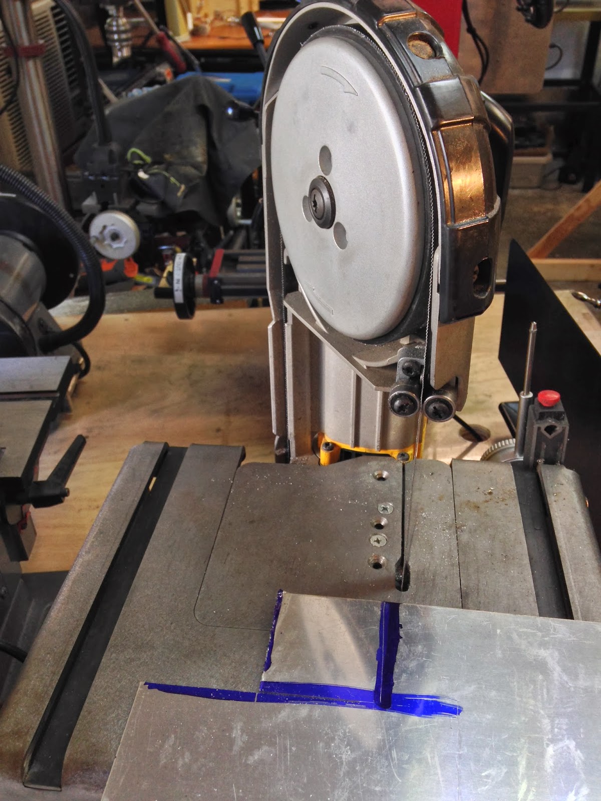
I had to make two back plates out of 0.063” 2024 aluminum, to be mounted opposite of the axles.


Cutting the blanks for the 2 back plates

Drilling starter holes


The axles themselves are beautiful chunks of machined aluminum anodized black.


Beautifully cut axles


Now, the plans would have you apply 3 plies of BID where the axles should go, and 3 more plies on the back side, where the aluminum plates would go, then the axles and the plates would be placed on the gear legs, and held up with clamps. All of this should be taking place about 8 feet up in the air, while on a ladder. 

Even if you could manage to hold on to this squishy and slippery sandwich, then you’d have to introduce two 2 foot carpenter squares, hold them perpendicular to the axles, and measure their relative distances at the axles, and at the 2 foot mark.

If the total difference was any more or less than 0.4” to 0.2” then, with your 5th hand perhaps, you should tighten or release the pressure on the strategically placed clamps, measure again, and repeat that cycle.

Conveniently the plans don’t go into too many details about how to achieve that, they just show a drawing of the squares floating in mid air


Good luck with that!


I tried all of that dry, without introducing the slippery epoxy, and could not do it. First of all the steel carpenter squares are too heavy and awkward, then there are way too many variables to have to contend with.

So, I decided to buy some lighter aluminum carpenter squares at Lowes, and try a hot glue gun on the axles, in order to fashion quarter moon-like seats, so to speak, for the squares to sit on while in contact with the axles. This would have helped by making it more difficult for the squares to slide off the axles. Little did I know how powerful the glue would prove to be.


Aligning the axle centerline with the aluminum carpenter square

Hot glue idea


Much to my surprise, the glue gripped the axles much more tightly than I expected, so I decided to give it a try, and see if it was strong enough to eliminate this one big variable from my plate.


Hot glue holding tight

Hot glue holding the square all on its own

Close up of the joint


It worked! Now I could just use a couple of loose 2x4 scraps to hold the long ends of the squares from sagging, and I was back in complete control of my measuring duties. 

The measurements revealed that a little more sanding was required to achieve a perfect geometry. This turned out to be very important, since I decided to drill the holes before fiberglassing, in order to use the actual bolts to help hold the whole “sandwich” up later. 


More sanding


Obviously, drilling the holes ahead of glassing is a very risky move, since the angle of the bolt holes cannot be modified, and that’s why I put so much effort into getting the sanding of the legs spot on.


28.5" from centerline to the edge of the square, at the axle station.

28.4" from the centerline, near the end of the square (the tower risers prevented me from measuring at the 2 foot mark)


I was hoping to use the axle's bolt holes as a drill guide, but all the drill chucks I own were too big to get close enough to the axle. I could have really used a 7" long 1/4” bit, but I didn’t have one, so I used a 1/4” center-punch to mark the holes locations, and a drill guide to drill as perpendicular to the leg as possible.


Holes center-punched and axle outline marked

Using a drill guide to drill perpendicular holes


A check of the distances with the axle bolted on, revealed no surprises.


Test fitting the axle


Later, I put the disk brake flange up there to get an idea of where the gear leg needed to be trimmed.


The gear leg below the brake flange will be trimmed off


Not unexpectedly, the AN4-22 bolts were too long, since I was still missing 6 plies of BID, but perhaps also because my brakes are a different brand from the original.


Bolts are too long, as usual.

Making it work for testing purposes


The real Loch Ness Monster


I just couldn’t resist mounting the wheel up there...


Finally something that slipped right on!

Half way there!


Next time I’ll be glassing this leg, then move on to the left leg.