Instrument panel (4.5 hrs)
In addition to going with a 2" wider cabin, I will raise the instrument panel by 1" in preparation for an extended nose, this will allow for a smoother curvature when looked at a 45˚ angle. All of this is pretty straight forward at this point, just push the sides out and up by 1". Conversely, adjustments to the layout of the panel components necessitate some strategic thinking.
I never had an issue with the size of the Long EZ seat, but I did with the elbow room, so I planned to enlarge the side consoles/armrests while keeping the flight controls in the same position relative to the aircraft centerline.
One additional item that just nagged at me, is the unequal size of the legs cutouts, which is directly related to the consoles width.
 |
| Typical Long EZ leg cutouts |
Due to the change in console width, a repositioning of the leg cutouts would also be necessary, and presented an opportunity to rethink this area.
My experience with the Long EZ mockup revealed the right leg cutout to be adequate, and the additional size of the left one not necessary. My decision therefore was to shrink the left cutout to match the size of the right one, and use the added space in the center post for a standby instrument, or two.
I have to admit to having been a bit apprehensive about this step, mostly because I had not yet come up with a good idea on how to precisely transfer the pattern to the foam. Up until now, my bulkheads consisted in reproducing measured dimensions to foam, not transferring patterns.
I decided to design my modified panel first, then figure out where to go from there. The quickest way to do this was to use tracing paper over the original design.
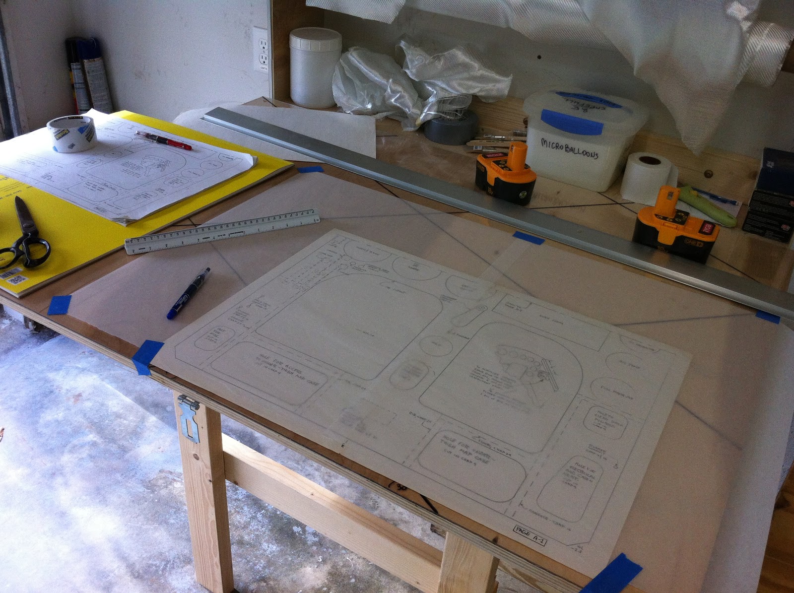 |
| Tracing paper over bottom half of instrument panel template |
Shifting the paper repeatedly, I traced each design element into the desired positions, and pretty soon I had a new wider panel, complete with identical leg cutouts.
 |
Modified panel |
The system I came up with to transfer the design from paper to foam, consisted of laying the tracing paper (with the drawing on it) over the foam, punching holes into both of them in strategic locations with a paperclip, removing the paper, and connecting the holes with a pen.
 |
Punching holes through paper and foam |
 | |
|
 |
Connecting holes with pen |
 |
Adding rounded corners |
It worked spectacularly, and as long as you punched the hole precisely, the resulting foam pattern would be just as precise.
 |
I knew all those high school technical drawing classes would come in handy one day |
After a quick trim, here’s the revised instrument panel:

Before proceeding to the glassing stage, I had to insert a piece of plywood into the foam for the fuel selector to attach to. This gets buried into the fiberglass, and will provide a solid anchor (compared to foam) for the screws to bite into.

The next step will involve epoxy, but before then I’ll take a moment to dream...

No comments:
Post a Comment