Face plate
Looking at all the holes in the current instrument panel, it became obvious that some additional glass work would be needed no matter what else I chose to do. Some holes needed to be closed and new ones opened. I decided move forward by cutting a big square hole into the existing panel and replace it with an aluminum plate. This would also allow me to do all of the work comfortably at home.
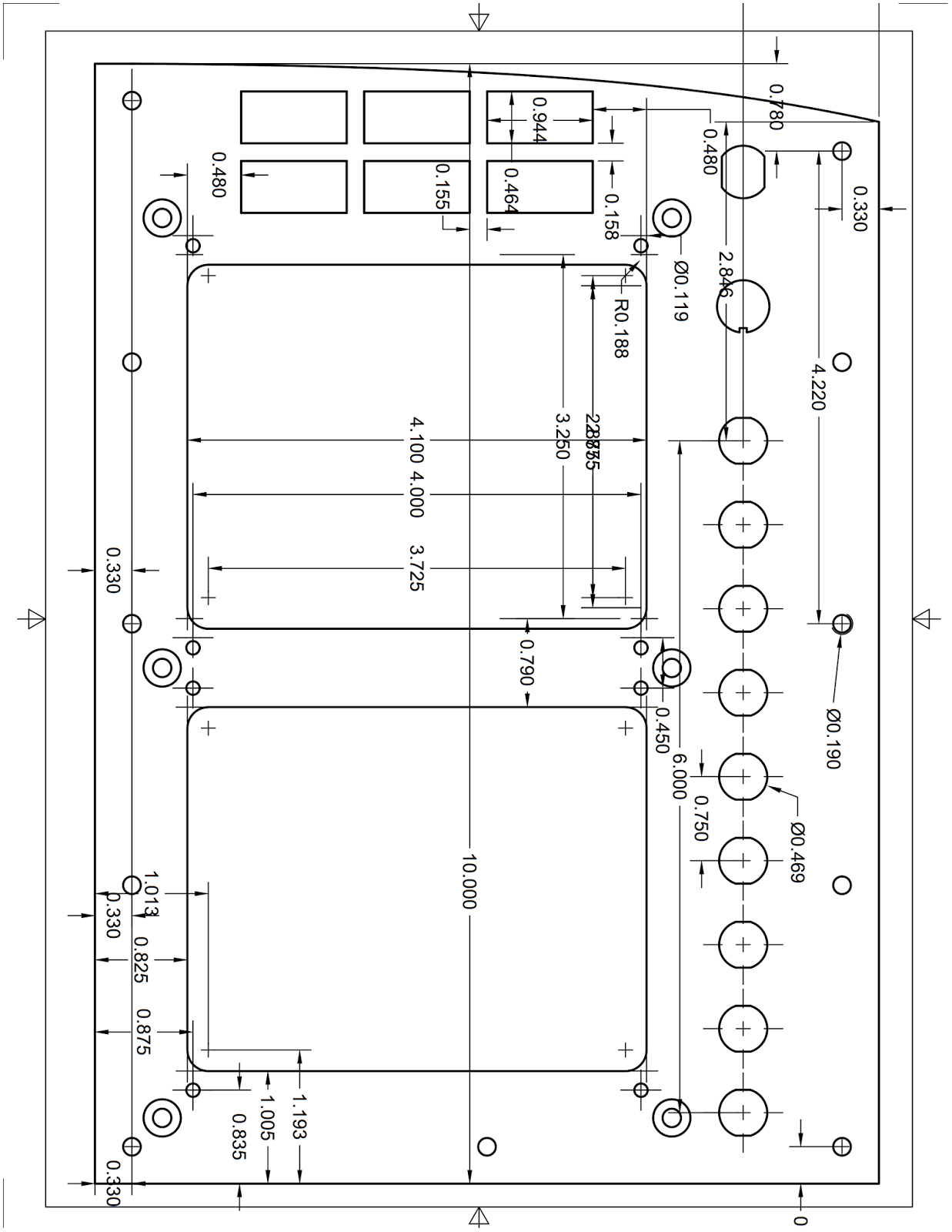
Here’s my initial CAD recreation of the plate/panel I am going for…
 |
| The bottom screen will be used as a map, of course. |
 |
| These Mini-APs are very shallow, and that includes the battery backup. |
 |
| I will have to replicate this design today (the top right will slope down a little) |
I decided to use 0.090” (2.3 mm) 2024 aluminum plate, but I only had a 0.063” (1.6 mm) on hand, so I started version #1 with that. I figured I’d have enough configuration changes or mistakes to warrant at least a redo or two, so I got on with it, while I put in an order for the thicker stuff.
 |
| Test fitting the plate after cutting the top by hand |
As usual my biggest problem was how to cut this big plate with my little mill.
 |
| Actual dimensions of the panel |
I chose to cut it in three separate setups, knowing full well that every setup takes forever, and reduces precision inversely to the setup time.
 |
| First cutting operation |
 |
| Op #2 |
 |
| Plate flipped on its back to final cutting |
This required making a fixture, so I reused the one I made for the brake heat shields, except I flipped it over for a fresh surface on which to drill a bunch of holes.
 |
| If this looks vaguely familiar, it's the brake heat shield fixture. |
 |
| Fixture flipped. Back in business! |
Op #1 went down with a hitch.
 |
| Looking pretty good, but a lot more work to be done. |
Ops #2 and #3 required careful, time consuming alignment using the just-cut machined surfaces and a dial test indicator. With that done, they also presented no real cutting challenge.
 |
| Op #2, circuit braker holes being cut. |
 |
| End of operation #2 |
 |
| With the plate flipped on its back and carefully aligned, op #3 could begin. |
 |
| The last operation only has to finish cutting the two EFIS holes |
 |
| Finished plate on top of the original drawing |
Finally, I got a chance to temporarily install the EFIS screens, switches, a couple of CBs, and the Korry-318 indicator lights, and check for issues.
 |
| Test fitting a few items |
 |
| All is well except for the bottom row of indicator lights |
Unfortunately my PFD hole was cut about 0.060” (1.5 mm) too high (my bad), and the second row of Korry-318 lights ended up too close to the PFD. I pushed them in half way anyway in order to take the above photo, but as I predicted I’ll have to cut this plate again.
Regardless, I used it to cut the wooden instrument panel, then I installed it, and ran some battery power to all the components for a real glamour shot.
 |
| All items powered, though not connected together yet. |


No comments:
Post a Comment