Shear web (8.2 hrs)
In the last post, I said I would talk more about the different ways the shear-web can be laid. There are really only two ways, the original approach using BID, and the modified approach (CP#25 LPC#26) which employs UNI. The nice thing about the newer method is that it saves 3.5 lbs (1.6 kg) of weight, while retaining the original strength.
 |
| Long EZ Plan Change #26 (shear-web is layup #5) |
Method #1 used 3 plies of BID at 45° with the usual 1” (2.5 cm) overlap. Method #2 uses only 2 plies of UNI also cut at 45°, these are butted to each other, not overlapped. Choosing the latter method to achieve the weight savings also commits you to modify layups #6 and #8.
I'd like to add one last word on the Long EZ Plan Change #26, just to put it in context.
LPC#26 was published in Canard Pusher newsletter #25, (dated July 1980), which was only the second newsletter to include the Long EZ design. This happened only four months after the Long EZ plans were released (March 1980), so we are talking about a modification that was done very early in the life of the airplane.
If we assumed that no one was able to build all the way to Chapter 14 during the first four months the plans were being sold, then we might deduce that there shouldn’t be any Long EZ out there using the older layup schedule, or at very least we could say that everyone (who read the CPs) was afforded the opportunity to use the lighter layup schedule.
I chose to go with the lighter schedule, thereby removing weight behind the center of gravity, a good thing since I’ll be later adding more weight there in the form of a heavier engine.
One byproduct of going with a thinner shear-web design is that the two spar-cap troughs I cut in the center-section spar last time using our templates, will now be slightly deeper than necessary.
Although I didn’t see this coming, it is not really a concern. Worst case scenario, I might have to add a layer of spar-cap UNI tape later on, to completely fill the troughs. In this situation, coming up short and having to add glass is preferable to coming up oversize, and having to shave structure off, as the maximum amount of removable material is set by the designer to 0.04" (1.0 mm).
Back to the sheer-web… nothing unusual going on here, just a bit of prep work…
 |
| This might get a little messy. Duct tape is good insurance against trouble. |
 |
| I made a template to help me draw where to cut on the UNI |
… then resin and hardener got mixed, and the clock started ticking…
 |
| Starting with the micro-slurry |
 |
| The first 3 UNI sheets butted (not overlapped) end to end on the spar |
 |
| Pure epoxy wetting the cloth. Black marker line I made along the UNI fiber starting to show. |
 |
| Starting on the center part. The black marker lines help me verify the 45° UNI orientation. |
 |
| First layer done. |
 |
| Last ply of the second layer going down. See the 90° Xs on the other two sections? |
 |
| Spar cap layup complete |
 |
| Shear-web close-up over the two left LWA4 |
I trimmed the UNI with a razor knife, and kept the fibers from being disturbed by pressing them down with a squeegee.
 |
| I razor trimmed the excess right away |
 |
| Same thing seen from the opposite end |
 |
| Proper orientation of the UNI is highlighted by the 90° X |
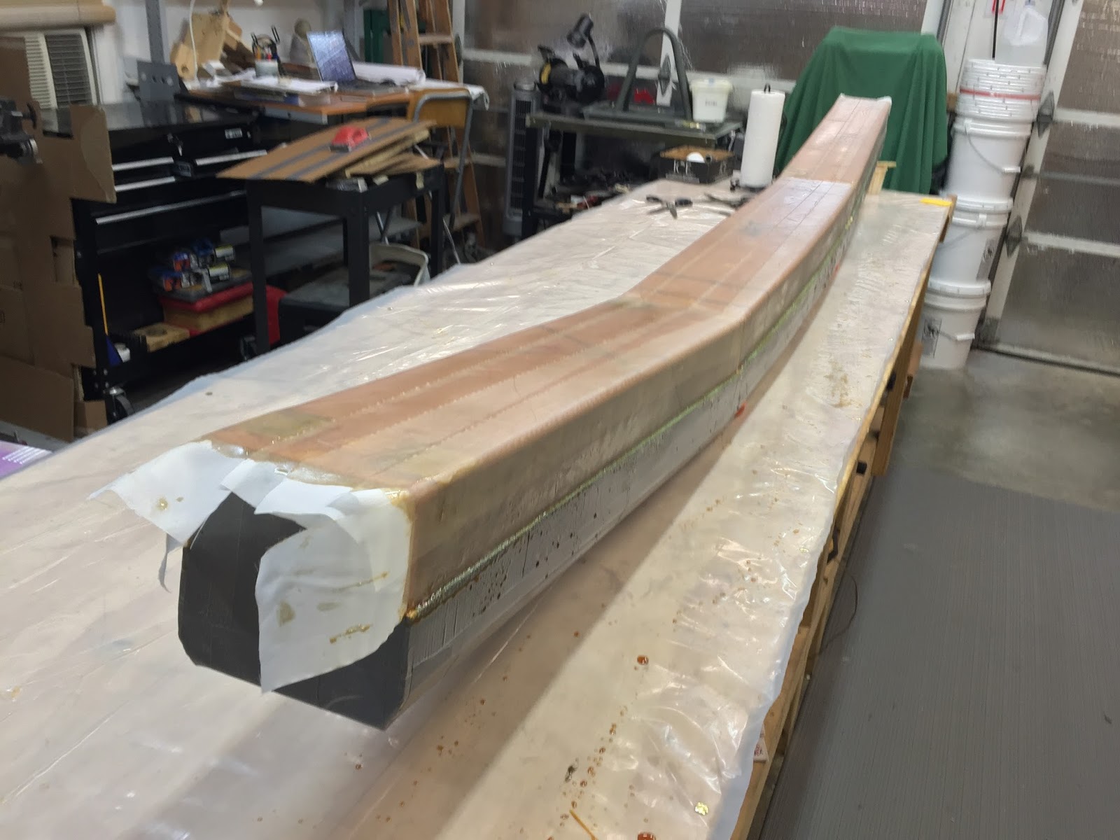
Because the two spar-caps and layup #6 will be attached to the shear-web, I peel-plied the whole thing.
 |
| This took a lot of peel-ply |
Peel-plying always leave a small amount of Dacron fibers that didn’t come off with the rest of the tape. Some light sanding helped them get off my spar at once.
 |
| Spar cap lightly sanded to remove leftover peel-ply strands |


No comments:
Post a Comment