Chronicling my Long EZ construction (and a few other things).
Disclaimer
This blog is for entertainment purposes only, and is not meant to teach you how to build anything. The author is not responsible for any accident, injury, or loss that occurs as a result of reading this blog. Read this blog at your own risk.
In the last post, I said I would talk more about the different ways the shear-web can be laid. There are really only two ways, the original approach using BID, and the modified approach (CP#25 LPC#26) which employs UNI. The nice thing about the newer method is that it saves 3.5 lbs (1.6 kg) of weight, while retaining the original strength.
Long EZ Plan Change #26 (shear-web is layup #5)
Method #1 used 3 plies of BID at 45° with the usual 1” (2.5 cm) overlap. Method #2 uses only 2 plies of UNI also cut at 45°, these are butted to each other, not overlapped. Choosing the latter method to achieve the weight savings also commits you to modify layups #6 and #8.
I'd like to add one last word on the Long EZ Plan Change #26, just to put it in context.
LPC#26 was published in Canard Pusher newsletter #25, (dated July 1980), which was only the second newsletter to include the Long EZ design. This happened only four months after the Long EZ plans were released(March 1980), so we are talking about a modification that was done very early in the life of the airplane.
If we assumed that no one was able to build all the way to Chapter 14 during the first four months the plans were being sold, then we might deduce that there shouldn’t be any Long EZ out there using the older layup schedule, or at very least we could say that everyone (who read the CPs) was afforded the opportunity to use the lighter layup schedule.
I chose to go with the lighter schedule, thereby removing weight behind the center of gravity, a good thing since I’ll be later adding more weight there in the form of a heavier engine.
One byproduct of going with a thinner shear-web design is that the two spar-cap troughs I cut in the center-section spar last time using our templates, will now be slightly deeper than necessary.
Although I didn’t see this coming, it is not really a concern. Worst case scenario, I might have to add a layer of spar-cap UNI tape later on, to completely fill the troughs. In this situation, coming up short and having to add glass is preferable to coming up oversize, and having to shave structure off, as the maximum amount of removable material is set by the designer to 0.04" (1.0 mm).
Back to the sheer-web… nothing unusual going on here, just a bit of prep work…
This might get a little messy. Duct tape is good insurance against trouble.
I made a template to help me draw where to cut on the UNI
… then resin and hardener got mixed, and the clock started ticking…
Starting with the micro-slurry
The first 3 UNI sheets butted (not overlapped) end to end on the spar
Pure epoxy wetting the cloth. Black marker line I made along the UNI fiber starting to show.
Starting on the center part. The black marker lines help me verify the 45° UNI orientation.
First layer done.
Last ply of the second layer going down. See the 90° Xs on the other two sections?
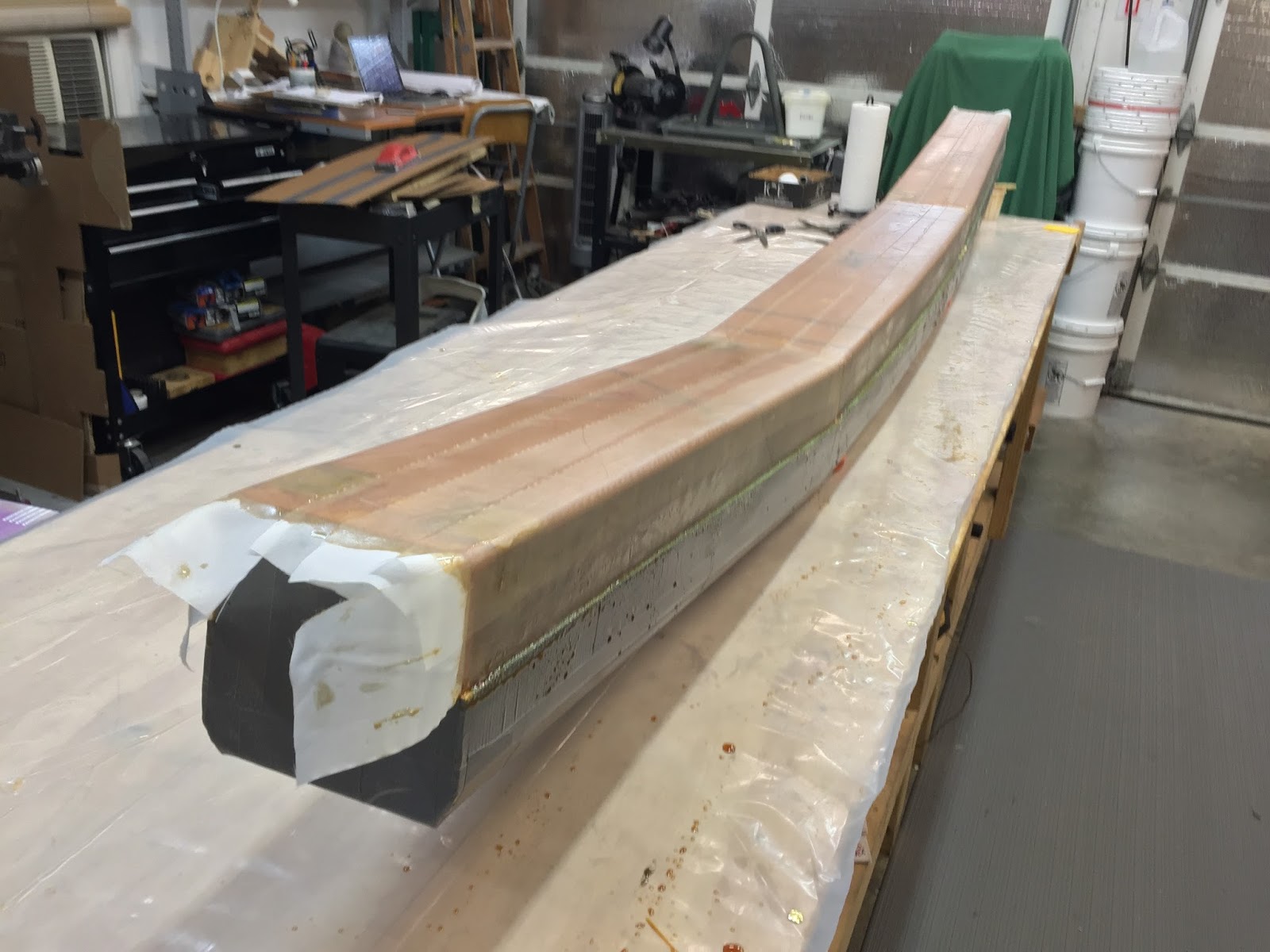
Spar cap layup complete
Shear-web close-up over the two left LWA4
I trimmed the UNI with a razor knife, and kept the fibers from being disturbed by pressing them down with a squeegee.
I razor trimmed the excess right away
Same thing seen from the opposite end
Proper orientation of the UNI is highlighted by the 90° X
Because the two spar-caps and layup #6 will be attached to the shear-web, I peel-plied the whole thing.
This took a lot of peel-ply
Peel-plying always leave a small amount of Dacron fibers that didn’t come off with the rest of the tape. Some light sanding helped them get off my spar at once.
Spar cap lightly sanded to remove leftover peel-ply strands
The shear-web is a fiberglass framework that ties the aft face of the spar to the top and bottom faces, creating a C-like structure that traverses the entire spar.
Shear-web highlighted in red (layup #5)
This interesting layup spanning three sides of the spar can actually be done in a couple of different ways, which I will discuss next time, because before we can even think of fiberglassing, there is quite a lot of precision foam carving business to attend to.
I will have to carve two differently shaped troughs on the spar, one on its top face, the other on the bottom. The shear-web will connect these two faces, then the troughs will be filled up by the very thick spar-cap layups that will be laid right over the top of the shear-web.
To help us in this task, the plans utilize a cunning strategy by giving us the profiles of the troughs in four different locations, in the form of templates to be carved out of any suitable material.
Center-section spar-cap templates
The builder’s next task is to basically sand until he’s blue in the face… I mean, until the templates fit.
Simple, right? Did I mention that the top trough has an irregular twist, or two?
Mmmm, this might require a 21st century approach (once more).
Of course, had I not banned Urethane foam from my plane, this task would have been a lot easier, but I digress. Let’s tackle one issue at a time, first we need to make the templates, then we’ll figure the rest out.
I had this idea of measuring up all the templates, and redraw them with a Computer Aided Design program. I reasoned I could print them on a brand new piece of paper, rather than cutting up my precious 35 years old yellowish drawings.
Then again, sometimes one would be better off not knowing how approximate the original drawings really are. Attempting to be precise (a prerequisite in CAD)... let’s just say that I couldn’t rely 100% on direct measurements, and a lot of crosschecking with dimensions in other pages proved to be necessary before I was able to settle on any values.
Measuring the templates
One of the biggest giveaways was the trough itself, supposedly a 3” section all the way through, it could be off by plus or minus 1/8” contingent on the template you measured. Anyway, I eventually got the data I needed to redraw reasonably accurate templates, with the most critical dimension being the depth of the trough.
The very important depth of the trough circled in red
However the process of cutting them with a scissor introduced a whole new level of uncertainty, sometimes the errors could become monumental depending on how well I was able to follow the lines. Then there was the “gluing the patterns to the wood” thing, followed by shaping on the belt sender.
Man, I had enough compounding errors to be off by a mile!
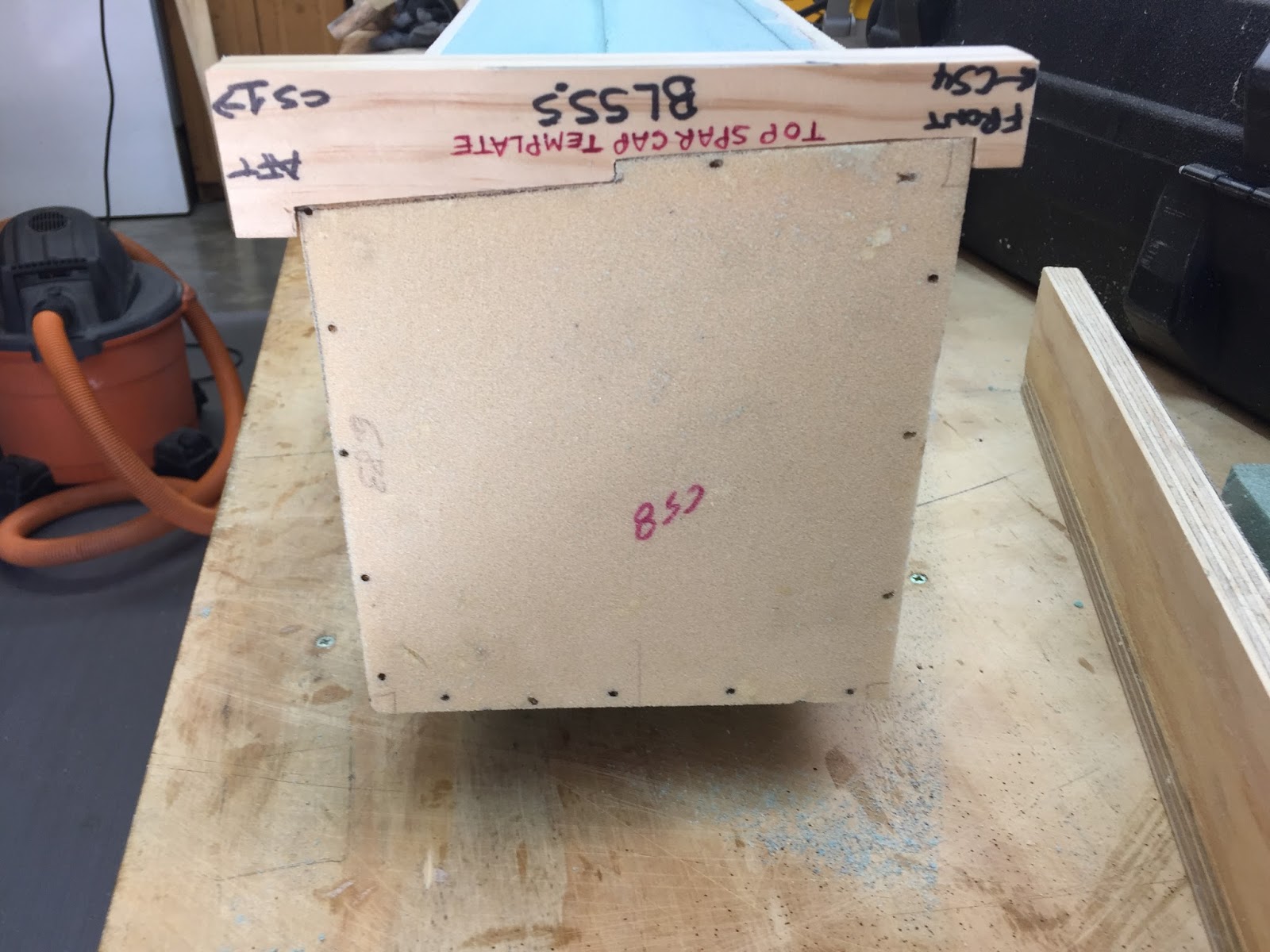
But I didn’t spend 6 months converting my mini-mill to CNC for nothing! These babies would get cut on the mill, and that was it! And since I had plenty of scrap wood, courteously supplied by Aircraft Spruce with every box of foam and sheet metal I ever bought, they would be made out of wood.
Making templates the easy way
I admit the CNC process produced a few failures, but that was mostly the operator’s fault, compounded by the newness of the Fusion360 CAD/CAM.
After some doing, I started getting what I was looking for, though in the end it probably took the same amount of time as if I had done them by hand.
Finally the CAD/CAM Gods had mercy on me
Most of the templates
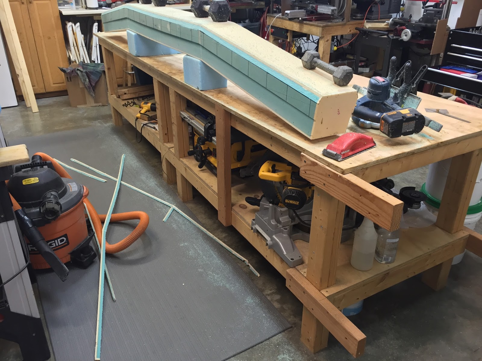
Using the templates' Butt Lines (horizontal distances from airplane centerline), I divided the top and bottom surfaces of the spar into sections span wise, and marked the depth to be achieved in the corner of each section. Using a router, I would cut only as deep as the shallowest depth found in that particular section to knock off the bulk of the foam, then sand it all to the proper depth by hand until the templates fit.
Top face divided into sections based on the templates BL
The center section (BL±15) is the easiest being evenly 0.50" (1.27 cm) down from the top
BL15 to BL25 is to be carved 0.40" (1.02 cm) down
BL25 to BL40 gets carved to 0.37" (0.94 cm), as that is the shallowest depth in this section.
BL40 to BL55.5 gets carved to 0.35" (0.89 cm), since this is the shallowest depth in the far section.
The carving occurred entirely on the back half of the top and bottom spar surfaces. However, starting at BL40 even the front part of the top surface got sanded down slightly. The bottom of the spar was slightly easier to figure out, since outboard of BL13 the trough tapered at a constant rate. So, I figured out the formula to calculate the depth of the trough at any chosen BL (form BL13 to BL55.5).
Depth of bottom trough(valid from BL13 to 55.5) = (55.5 - BL)*0.00541 + 0.16
I chose to apply it every 5” (12.7 cm), and marked the shallowest depth for that small section on the foam, to be later removed with the router, and transitioned down to the next section by hand.
Depth of the trough at BL±13 is a constant 0.39" (0.99 cm)
0.352" = (55.5 - BL20)*0.00541 + 0.16 = 8.94 mm 0.325" = (55.5 - BL25)*0.00541 + 0.16 = 8.25 mm
0.298" = (55.5 - BL30)*0.00541 + 0.16 = 7.57 mm 0.271" = (55.5 - BL35)*0.00541 + 0.16 = 6.88 mm
0.244" = (55.5 - BL40)*0.00541 + 0.16 = 6.20 mm 0.216" = (55.5 - BL45)*0.00541 + 0.16 = 5.49 mm
0.189" = (55.5 - BL50)*0.00541 + 0.16 = 4.80 mm 0.162" = (55.5 - BL55)*0.00541 + 0.16 = 4.11 mm
With all cuts to be made accounted for, I pulled out the router, hooked up the vacuum attachment, unpacked the edge guide (purchased 5 years ago and never used), and took the plunge (pun intended).
This is how I fine tuned the router depth (a lot more foam was sacrificed to the altar of accuracy).
The vacuum attachment is so intrusive, but it is very effective at removing foam dust.
With the edge guide set to 3" (7.6 cm), cutting all the way to the black line was child's play.
The rest of the foam removal was to be done by hand
I smoothed the leftover steps with a sanding block until the templates for BL0 and BL25 fit.
The straight sections of the trough were completed first
Then started sanding the outer sections downward twist.
Sanding the downward twist outside of ±BL25, required a lot more attention.
The twist at BL40 is pretty small
The twist at BL55.5 is a lot more pronounced
Before I could match the remaining two templates (BL40 and BL 55.5) with the trough, I had to work on the twist zone of the top spar face's forward half. I marked the foam, and blended it all by hand.
The outer forward section of the top face also has a small progressive twist down.
This area was sanded down by hand pretty easily using the lines and templates as guides.
This are the results of all the work performed.
Top spar cap trough at BL55.5 right of centerline
Top spar cap trough at BL40 right of centerline
Top spar cap trough at BL25 right of centerline
Top spar cap trough at BL0, right on centerline.
Top spar cap trough at BL25 left of centerline
Top spar cap trough at BL40 left of centerline
Top spar cap trough at BL55.5 left of centerline
Top spar cap trough completed
Later, I flipped the spar over, and went to work on the bottom face in the same manner with the router and the sanding block.
Bottom spar cap trough sections to be carved with the router
Trying very hard to avoid damaging the spar
Showing the many thin step ups, and the corner that had to be recut without the edge guide.
Selfie taken while smoothing the steps left by the router with the sanding block
Bottom spar cap trough at BL55.5 left of centerline
Bottom spar cap trough at BL40 left of centerline
Bottom spar cap trough at BL25 left of centerline
Bottom spar cap trough at BL0, right on centerline.
Bottom spar cap trough at BL25 right of centerline
Bottom spar cap trough at BL40 right of centerline
Bottom spar cap trough at BL55.5 right of centerline
A little trim job was required on the front section of the spar as well. The square corners had to be blunted by removing a 1” x 0.5” (2.5 x 1.7 cm) triangle section.
Marking the corners of the spar to be removed
Showing the drawings with the front (top in the photo) corners missing
Improvised jig for cutting the corners
Testing the jig effectiveness
Corners cut in one motion laying on the floor
Cornerless spar
Same thing, opposite view.
Since I put off finishing all of the spar’s metal plates, I still had to do some edge rounding on the mill.
Making a 0.200" (5 mm) radius round corner with the CNC mill
I say... "Smoke 'em if you got 'em"
Finally, I identified all the locations of the metal plates inside the spar, and marked them on the foam.
Marking the inner LWA1 locations on the outside of the spar, for LWA4 and LWA5 placements.
Then started removing the foam and sanding down to bare fiberglass.
I tried with the router, but it was difficult, dangerous, and messy.
At least the fit was good
The quickest way to remove the foam turned out to be braking chunks off with the razor, after cutting along the perimeter.
This was far too easy
It took 30 seconds at most, though it required some sanding afterward.
After a quick test fit of all the plates, I alodined them and permanently installed them.
All the plates fit
4 LWA4 and 2 LWA5 drying after the Alodine treatment
Wetting with pure epoxy
Adding flox
Saran wrap topping
A few weights to keep things tight
A little aluminum scrap doubles as standoff for the chuck
LWA5 feeling the weight
LWA4 being lightly pressed
Using a small aluminum block to keep the weight off the foam, and on LWA4.
I let the flox cure overnight, and the next morning sanded the edges of the foam to match the roundness of the tabs. In the process, most of the Alodine got sanded away as well, so I could have easily skipped that step the night before.
A little cleanup was necessary in the morning
Rounding the corners of the foam ended up stripping the Alodine
At this point, the coast was finally clear for fiberglassing. As an aside, I was a bit shocked when I stood up the spar and nearly hit the ceiling. The spar is huge, yet incredibly light.