Pedal oops! (15.9 hrs)
In the past I mentioned that the main purpose of this blog is to have as many eyes looking out for my mistakes as possible, and once again the concept has proven its worth.
Yes, I have made another mistake, but luckily this one is only going to cost me a few more days of work.
Someone brought to my attention that the correct mechanical advantage for the Matco master cylinder should be 2.5 to 1, and my pedals did not look right. After investigating the issue I discovered (or better... rediscovered) that to be correct, and my geometry to be off.
Crap!
I remember considering this very fact at the beginning, but months later, as I started shortening the bracket, I had completely forgotten about it.
With the current set up, the best I could achieve using the lowest flange hole was just a 2.0 to 1 ratio. While this would have provided less hydraulic pressure to the brake pads, it might have still worked ok given my choice of oversized brakes, however I was not willing to paint myself in a corner from the get go.
In order to fix this, the flanges would have to be moved, and the brackets redesigned and machined once again, this time 1” (2.5 cm) longer.
Here we go again…
I found the short welds on the flanges to be amazingly strong, I had a very hard time getting the tabs off, and had to grind through most of the welds before the flanges gave up.
 |
| Grinding the flange off the pedal |
 |
| These welds turned out to be incredibly strong |
 |
| Eventually the Dremel won |
Since the pedals are 7” (17.8 cm) long, the new hinge position for the piston needs to be at 2.8” (7 / 2.5 = 2.8).
In order to reliably reproduce this measurement, and to help hold the flange while I tacked it with the TIG welder, I drilled two holes 2.8” (7.1 cm) apart in a piece of plywood (first thing within reach) and ran some bolts through them, using washers as spacers to align the flange with the center of the pedals.
 |
| Improvised wooden jig |
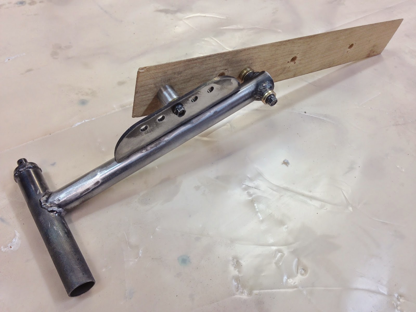 |
| Jig made it possible to line up the components with precision |
 |
| As before, I had to preheat the flange in order to facilitate the welding to the thinner tube. |
I knew the wood would not last under the heat of the welding, but I only needed it to endure two such treatments. After removing the wooden jig, I continued on with the welding.
 |
| Same flange, new position. We'll call this version #2. |
 |
| Here you can see the lowered flange compared to the original. This increases the mechanical advantage. |
The last step on this process was machining the longer brackets.
 |
| Braket ⅓ machined used to verify the desired pedal angle |
 |
| Finished brake assembly (pedal version #2, bracket version #3) |
 |
| Can you see why the bracket needed to be lengthened? After lowering the flange the pedal laid far too flat. |
It seems that I always end up building at least 3 versions of everything I design, and the brake brackets turned out to be no different.

No comments:
Post a Comment